
Improved pressing plate bolt structure of sawing machine clamp

A bolt structure and improved technology, applied in the direction of clamping, manufacturing tools, supports, etc., can solve the problems of affecting the efficiency of operation, loosening of round steel or steel pipe, unsafe sawing and other problems, so as to improve convenience and avoid pressure The tight contact surface is small to avoid the effect of uneven pressing force

Pending Publication Date: 2021-08-03
CHENGXI SHIPYARD
View PDF0 Cites 0 Cited by
  • Summary
  • Abstract
  • Description
  • Claims
  • Application Information

AI Technical Summary

Problems solved by technology

[0004] First, the clamping bolts of the sawing fixture usually use conventional clamping bolts, which require a hexagonal wrench or an adjustable wrench during operation. Frequent assembly and disassembly will cause the wrench to slip and turn round.
In addition, because the wrench is not connected with the fixture, it is easy to waste time when looking for a wrench temporarily during operation, thus affecting the efficiency of the operation
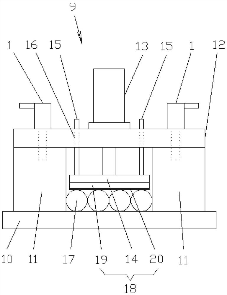
[0005] Second, when multiple round steel or steel pipes are clamped together, the clamping force is uneven, and some round steel or steel pipes are prone to loosening, which will lead to unsafe hazards during sawing and damage the saw blade

Method used


Image

  • Improved pressing plate bolt structure of sawing machine clamp
  • Improved pressing plate bolt structure of sawing machine clamp
  • Improved pressing plate bolt structure of sawing machine clamp

Examples


Embodiment Construction

[0037] The specific implementation manners of the present invention will be further described below in conjunction with the drawings and examples. The following examples are only used to illustrate the technical solution of the present invention more clearly, but not to limit the protection scope of the present invention.

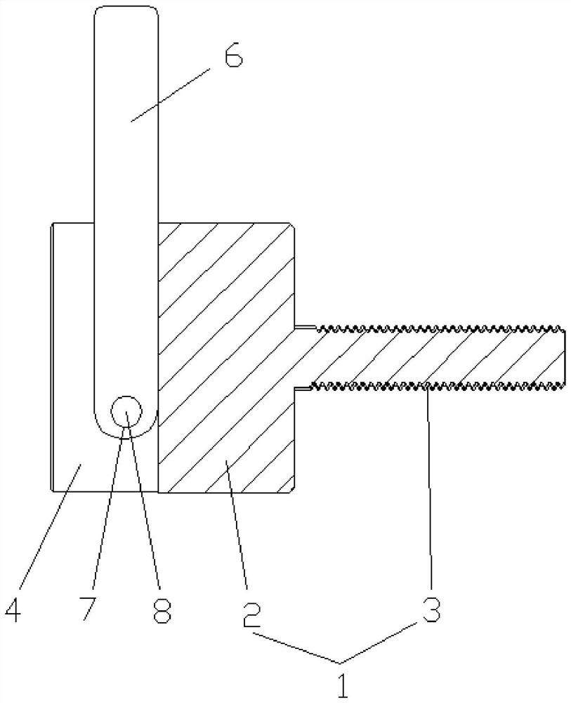
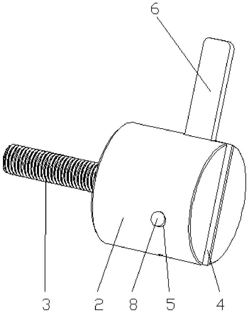
[0038] Such as Figures 1 to 5 Shown is an embodiment of an improved clamping bolt structure of a sawing machine clamp of the present invention, including a special clamping bolt 1 arranged on the sawing clamp, and the special clamping bolt 1 includes a cylindrical bolt head 2 and an axially integrated The screw rod 3 that is connected to one end of the cylindrical bolt head 2, the other end of the cylindrical bolt head 2 is provided with a groove body 4, and the outer circle of the cylindrical bolt head 2 is provided with a groove that passes through the groove body. 4 side and perpendicular to the first pin hole 5 on the side of the tank 4, a lever 6 is ...


PUM


Abstract

The invention relates to the technical field of technological equipment, in particular to an improved pressing plate bolt structure of a sawing machine clamp. The improved pressing plate bolt structure comprises a special pressing bolt arranged on the sawing machine clamp, and the special pressing bolt comprises a cylindrical bolt head and a screw axially and integrally connected to one end of the cylindrical bolt head. A groove body is formed in the other end of the cylindrical bolt head, a first pin hole which penetrates through the side face of the groove body and is perpendicular to the side face of the groove body is formed in the outer circle of the cylindrical bolt head, a lever is connected into the groove body, a second pin hole is formed in the lever, and the lever and the groove body are rotationally connected through a pin inserted into the first pin hole and the second pin hole. According to the improved pressing plate bolt structure of the sawing machine clamp, the operation efficiency is improved, and the safety and reliability of operation are improved.

Description

technical field [0001] The invention relates to the technical field of process equipment, in particular to an improved clamping plate bolt structure of a sawing machine fixture. Background technique [0002] The sawing fixture is a clamping device installed on the sawing machine to clamp and fix the workpiece. Among the types of workpieces processed by sawing machines, the most common are round steel and steel pipes. During processing, the round steel or steel pipe is pressed and fixed on the worktable of the sawing machine by the jig of the sawing machine, and then the round steel or steel pipe is cut into a specified length by the saw blade on the sawing machine. Conventional sawing machine clamps usually can only clamp a single round steel or steel pipe; in order to improve the efficiency of sawing machine processing, an improved sawing machine clamp has also appeared, which can clamp and fix multiple round steels or steel pipes at one time. [0003] But the sawing mach...

Claims


Application Information

Patent Timeline
Patent Type & Authority Applications(China)
IPC IPC(8): B23Q3/08
CPCB23Q3/064B23Q3/082
Inventor 徐晓松周志刚肖建建邓建琴蒋吉
Owner CHENGXI SHIPYARD
Learn More