
Cooling unit, method for manufacturing cooling unit, and structure

A technology of cooling unit and fine concave-convex structure, applied in cooling/ventilation/heating renovation, electrical components, electrical solid devices, etc., can solve the problems of refrigerant leakage, deformation of cooling unit, submerged circuit components, etc.

Inactive Publication Date: 2021-07-30
MITSUI CHEM INC
View PDF4 Cites 0 Cited by
  • Summary
  • Abstract
  • Description
  • Claims
  • Application Information

AI Technical Summary

Problems solved by technology

[0004] However, in such a cooling system, there is a possibility that the cooling unit is deformed due to external impact or deterioration, the sealing structure including the refrigerant flow path constituting the cooling unit collapses, and the refrigerant leaks.
For example, in the case of secondary battery components, leakage may cause a short circuit of the electrodes
In addition, there is a possibility that the refrigerant leaks and floods the circuit components on the substrate

Method used


Image

  • Cooling unit, method for manufacturing cooling unit, and structure
  • Cooling unit, method for manufacturing cooling unit, and structure
  • Cooling unit, method for manufacturing cooling unit, and structure

Examples


preparation example Construction

[0124] 1. Preparation of the resin platter 3

[0125] 2. Additional securing of the elastic pad 4

[0126] 3. Preparation of the metal plate 2 with the elastic gasket 4 bonded by injection or adhesive bonding

[0127] 4. Mechanical connection between the top surface of the side wall of the resin tray 3 and the metal plate 2 via a gasket

[0128] In the method A, a method (adhesive bonding) in which the metal plate 2 is bonded to a belt-shaped or ring-shaped elastic spacer 4 separately prepared by injection molding or other molding means through an adhesive agent and molded as a representative example is mentioned. . Method A preferably includes a step of applying an adhesive to the fine unevenness structure on the surface of the metal plate 2 by a known method.

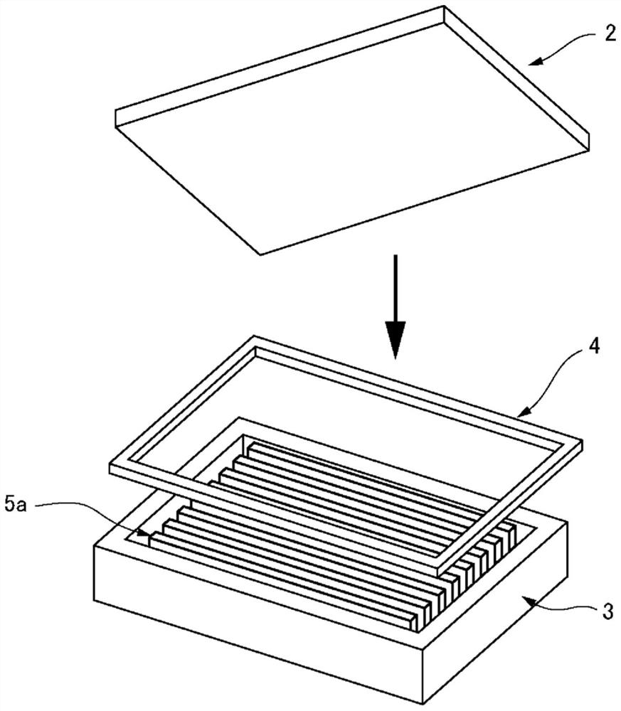
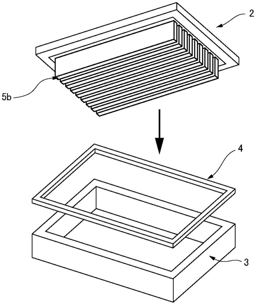
[0129] In method B, the cooling unit 1 according to this embodiment is assembled by mechanically connecting the resin platter 3 prepared by the method described above to the metal plate 2 with the elastic gasket. ...

Embodiment 1

[0160] The die for the leak test was attached to J85AD110H manufactured by Nippon Steel Works, and the surface-roughened aluminum alloy plate M1 obtained by the method described above was set in the die. Next, in the mold, the above-mentioned resin composition A1 was injection-molded under the conditions of a cylinder temperature of 190°C, a mold temperature of 40°C, an injection speed of 25mm / sec, a dwell pressure of 80MPa, and a dwell time of 10 seconds. , and a composite structure formed of the surface-roughened aluminum alloy plate M1 and the bonding pad composed of the above-mentioned resin composition A1 was produced. Furthermore, a joint gasket made of the above-mentioned resin composition A1 formed in advance was mechanically connected to the above-mentioned surface-roughened aluminum alloy M1 by screws, thereby obtaining a test piece for a leak test. A cross-sectional photograph of the boundary between the bonding pad and the metal plate in the obtained test piece is ...


PUM


Abstract

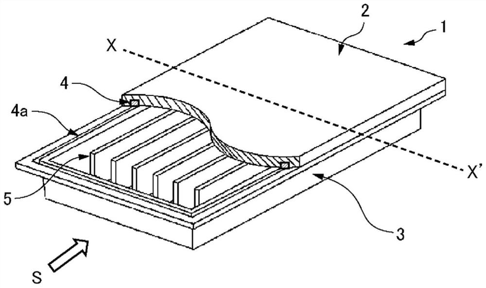
A cooling unit (1) is provided with a resin tray (3), a metal plate (2) provided on one surface of the resin tray (3), and flow path-forming ribs (5) provided in a space between the resin tray (3) and the metal plate (2). A top surface portion (3b) of a side wall portion (3a) of the resin tray (3) and the metal plate (2) are mechanically fastened together with an elastic packing (4) therebetween. The elastic packing (4) includes a joint packing joined to a surface of the metal plate (2). A micro-irregular structure is formed on the surface of the metal plate (2) in at least the portion where the surface is joined with the joint packing.

Description

technical field [0001] The present invention relates to a cooling unit, a method for manufacturing the cooling unit, and a structure. Background technique [0002] In recent years, the miniaturization of electronic devices and secondary battery modules has rapidly progressed, and the importance of heat management has increased as the heat generation per unit volume (or unit area) has increased. Heat generation causes the temperature of the main body of the device and the main body of the battery to rise. Semiconductor devices that play a central role in the operation of electronic equipment are very sensitive to temperature, and the temperature rise of the equipment will cause a decrease in operating efficiency, malfunction, and failure. In addition, for secondary batteries, a high heat state exceeding the upper limit of the operating temperature range may degrade capacity, increase internal resistance, or put the battery in a dangerous state such as explosion. Therefore, ...

Claims


Application Information

Patent Timeline
Patent Type & Authority Applications(China)
IPC IPC(8): H01L23/473H05K7/20
CPCH05K7/20254H01L23/4006H01L23/3737H01L23/3736H01L23/3672Y02E60/10H01M10/613H01M10/6556H01M10/6551H01L23/473H05K7/20336F28D15/0233H05K7/20281
Inventor 栗谷川瑞枝木村和树中岛慎治富永高广
Owner MITSUI CHEM INC
Learn More