Communication terminal device and communication system
A communication terminal and communication system technology, which is applied in the field of communication terminal devices and communication systems, can solve problems such as narrow directivity, inability to maintain communication status, and decrease in received signal strength, and achieve the effect of stable communication quality
- Summary
- Abstract
- Description
- Claims
- Application Information
AI Technical Summary
Problems solved by technology
Method used
Image
Examples
Embodiment approach 1
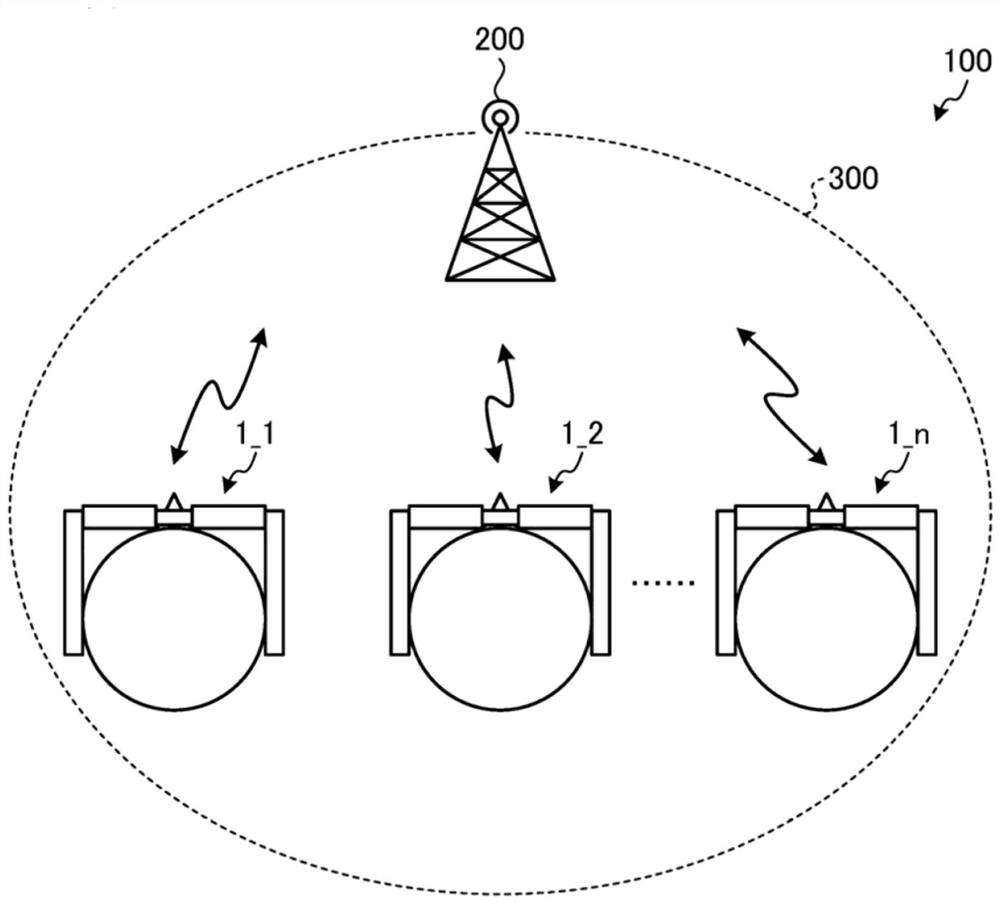
[0041] figure 1 It is a schematic diagram showing a schematic configuration of the communication system of the first embodiment. like figure 1 As shown, the communication system 100 of the present embodiment is constructed of a plurality of communication terminal devices 1_1, 1_2, ..., 1_n (nature) disposed within the coverage area 300 of the radio base station 200.
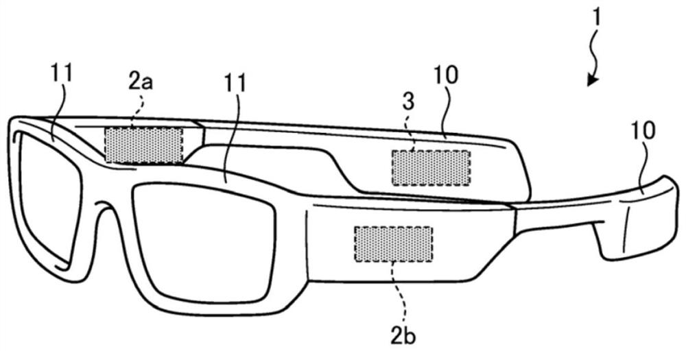
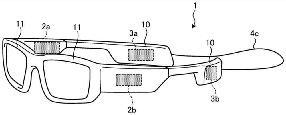
[0042] In the present invention, the communication terminal apparatus 1_1, 1_2, ..., 1_n is an AR terminal that implements the enhanced reality (AR: AUGMENTEDREALITY) function, for example, an opaque communication terminal device equipped with an optical transmitted display. Hereinafter, the communication terminal devices 1_1, 1_2, ..., 1_n are simply referred to as "communication terminal device 1" in the case where the communication terminal devices 1_1, 1_2, ..., 1_n is not required.
[0043]Various information is distributed from the wireless base station 200 to each communication terminal device 1_1, 1_2, ..., ...
Embodiment approach 2
[0130] Figure 13 A diagram showing an example of a block structure of the communication terminal device of the second embodiment. like Figure 13 As shown in the communication terminal apparatus 1a of the second embodiment, in addition to the structure of the first embodiment, there is provided a first coupling circuit (COP1) 5a and the second coupling circuit (COP2) 5b. Further, the schematic configuration of the communication system 100 and the operation flow chart of the communication terminal device 1a are the same as those of the first embodiment, and thus the description thereof will be omitted. in addition, Figure 13 The block structure shown is Figure 2A and Figure 4A The first example of the first example shown, but it can also be Figure 2b and Figure 4b The second example of the second case is compared.
[0131] Figure 14A It is a first diagram showing an example of a block structure of the first coupling circuit and the second coupling circuit of the second embodiment....
Embodiment approach 3
[0141] Figure 15 It is a diagram showing an example of a block structure of the communication terminal device of the third embodiment. like Figure 15 As shown, in the communication terminal device 1b of the third embodiment, the following structure is employed: by communication between the first coupling circuit (COP1) 7A and the second coupling circuit (COP2) 7b, the transfer is made. Further, since the schematic configuration of the communication system 100 and the operation flow chart of the communication terminal device 1b are the same as those of the first embodiment, the description thereof will be omitted.
[0142] Figure 16A It is a first diagram showing an example of a block structure of the first coupling circuit and the second coupling circuit of the third embodiment. Figure 16B It is a second diagram showing an example of the block structure of the first coupling circuit and the second coupling circuit of the third embodiment.
[0143] In the first coupling circuit 7...
PUM
 Abstract
Description
Claims
Application Information
 - R&D
- Intellectual Property
- Life Sciences
- Materials
- Tech Scout
- Unparalleled Data Quality
- Higher Quality Content
- 60% Fewer Hallucinations
Browse by: Latest US Patents, China's latest patents, Technical Efficacy Thesaurus, Application Domain, Technology Topic, Popular Technical Reports.
© 2025 PatSnap. All rights reserved.Legal|Privacy policy|Modern Slavery Act Transparency Statement|Sitemap|About US| Contact US: help@patsnap.com


