Gas meter

A gas meter and gas technology, applied in measuring devices, instruments, measuring flow/mass flow, etc., can solve the problems of low safety in use and low production efficiency of gas meters, and achieve high safety, good resistance to external force, and good sealing performance effect

Pending Publication Date: 2021-07-30
郑州安然测控技术股份有限公司
View PDF11 Cites 0 Cited by
  • Summary
  • Abstract
  • Description
  • Claims
  • Application Information

AI Technical Summary

Problems solved by technology

[0005] The purpose of the present invention is to provide a gas meter to solve the technical problems of low production efficiency and low safety in use of gas meters in the prior art

Method used


Image

  • Gas meter

Examples


specific Embodiment 1

[0034] Specific embodiment 1 of the gas meter provided by the present invention. In this embodiment, the ultrasonic gas meter is taken as an example to introduce and illustrate the specific structure of the gas meter in the present invention. In other embodiments, the gas meter can also be other outlets. Structured gas meters, such as membrane gas meters.

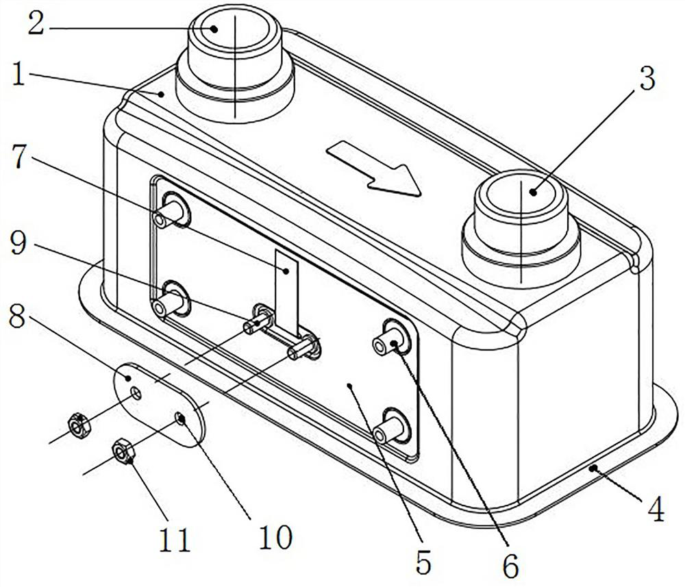
[0035] The gas meter has a casing. In this embodiment, the casing is an upper and lower split structure, including an upper casing 1 and a lower casing. The structure of the upper casing 1 is as follows: figure 1 As shown, the cross section of the upper shell 1 is rectangular, the top surface is provided with an air inlet port 2 and an air outlet port 3, the lower part is a shell mouth for docking with the lower shell, and there is a circle at the shell mouth for connecting with the lower shell. The valgus edge 4 that the body shell mouth place is turned over cooperates. The inner cavity of the casing is used to accommodat...

specific Embodiment 2

[0041] The specific embodiment 2 of the gas meter provided by the present invention differs from the embodiment 1 mainly in that in the embodiment 1, the sealant is applied to the opening of the wire hole to realize the sealing of the outlet structure. In this embodiment, A seal is set between the data transmission line and the inner wall of the wire hole, specifically, a rubber sealing ring is installed on the data transmission line to realize the sealing of the outlet structure. The size of the rubber sealing ring meets the requirements of the pressure plate. compression deformation. Of course, in other embodiments, a sealing ring can be placed on the cable hole or a sealing gasket can be placed in the groove, and the data transmission line can pass through the opening of the sealing ring or the sealing gasket.

specific Embodiment 3

[0042] The specific embodiment 3 of the gas meter provided by the present invention is mainly different from the embodiment 1 in that in the embodiment 1, the shell is a split structure up and down, and in this embodiment, the shell is a split structure in front and rear or left and right.


PUM


Abstract

The invention relates to a gas meter. The gas meter comprises a shell which is provided with a gas inlet connector and a gas outlet connector, wherein a measuring assembly is arranged in the shell and communicated with the gas inlet connector and the gas outlet connector, gas flows through the measuring assembly to measure the gas flow, and a metering control device with a display function is arranged outside the shell and used for processing the measuring result of the measuring assembly; a data transmission line is connected with the measuring assembly and the metering control device with the display function so as to transmit a result measured by the measuring assembly to the metering control device with the display function, a wire passing hole is formed in the shell, and the data transmission line is led out through the wire passing hole and is bent towards a wiring end of the metering control device with the display function along the surface of the shell; the fit between the data transmission line and the wire passing hole is sealed with sealant or a seal, the gas meter further comprises a pressing plate for pressing and covering the wire passing hole and pressing and positioning the data transmission line, the data transmission line is pressed through the pressing plate, the sealing structure is protected while the data transmission line is positioned, and therefore the gas meter has better sealing performance and is convenient to assemble.

Description

technical field [0001] The invention relates to a gas meter. Background technique [0002] The gas meter includes a measuring component located inside the housing and a metering control device with a display function located outside the housing. result. Taking the membrane gas meter as an example, the flow results measured by its measuring components are mainly transmitted to the metering control device with display function through magnetic transmission and shaft transmission to transmit mechanical signals. [0003] Unlike membrane gas meters, which mainly transmit mechanical signals inside and outside, the gas volume measured by the measurement components of ultrasonic gas meters is transmitted to the metering control device with display function in the form of electrical signals. For ultrasonic gas meters, in the prior art The transmission of electrical signals from the inside to the outside is mainly carried out by using the structure and method of leading out the adap...

Claims


Application Information

Patent Timeline
Patent Type & Authority Applications(China)
IPC IPC(8): G01F1/66G01F15/14G01F15/06
CPCG01F1/662G01F1/667G01F15/14G01F15/065G01F15/068
Inventor 冯德军周文辉徐宗云谢伟陈媛媛曾楚文胥凯强杨志豪唐宏伟王智渊李娟张青松陈璇张静伍勇丽李小磊刘小涛谭峰敏曹登高陈晶晶马云梁会珍李友能王帅王霞马伟力乔磊左孝堂王晓丽王丹丹宋丹
Owner 郑州安然测控技术股份有限公司
Why Eureka
Try Eureka