
OCT and fluorescence composite microscopic endoscopic imaging system

An imaging system and fluorescence technology, applied in endoscopy, analysis using fluorescence emission, medical science, etc., can solve inconvenient use, image joint diagnosis, inability to realize fluorescence microscopy and OCT in situ microscopic image superimposition, etc. problem, to achieve the effect of overcoming the large size of the probe and facilitating image fusion

Pending Publication Date: 2021-07-30
SUZHOU INST OF BIOMEDICAL ENG & TECH CHINESE ACADEMY OF SCI
View PDF0 Cites 2 Cited by
  • Summary
  • Abstract
  • Description
  • Claims
  • Application Information

AI Technical Summary

Problems solved by technology

At present, fluorescence microscopic imaging and optical coherence tomography are used independently in surgery, and the probe needs to be replaced in the combined use, which causes great inconvenience in use and cannot achieve in-situ image superposition for joint diagnosis
Yang Guangzhong’s team at Imperial College of Technology designed a composite microscopic probe for fluorescence microscopy and OCT, which solved the problem of changing the probe and increased the ease of use of the probe; The superposition of in-situ microscopic images; and it has not been integrated and optimized at the system level, and it is still two separate systems, which has great inconvenience in system control, synchronization of imaging and display, and real-time fusion of later images

Method used


Image

  • OCT and fluorescence composite microscopic endoscopic imaging system
  • OCT and fluorescence composite microscopic endoscopic imaging system
  • OCT and fluorescence composite microscopic endoscopic imaging system

Examples


Embodiment 1

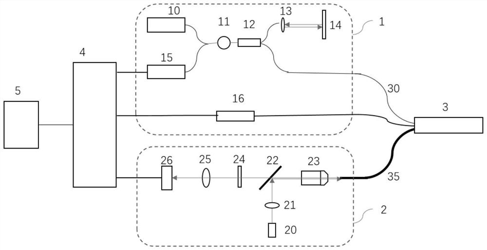
[0033] Such as Figure 1-3 As shown, an OCT and fluorescence composite microendoscopic imaging system in this embodiment includes: an OCT module 1, a fluorescence microscope module 2, a shared microprobe 3 and an image processing device 4;

[0034] The microprobe 3 includes an OCT optical fiber 30, an OCT imaging objective lens 31, a MEMS vibrating mirror 32, a dichroic prism 33, a fluorescence microlens 34, and an imaging optical fiber 35;

[0035] The probe light emitted by the OCT module 1 passes through the OCT optical fiber 30 and the OCT imaging objective lens 31 in turn, then reaches the MEMS vibrating mirror 32, and then is reflected to the sample by the dichroic prism 33, and the probe light reflected by the sample returns to the OCT module 1 through the original path, and finally Realize OCT imaging by image processing device 4;

[0036] The excitation light emitted by the fluorescence microscope module 2 sequentially passes through the imaging fiber 35 and the fluo...


PUM


Abstract

The invention discloses an OCT and fluorescence composite microscopic endoscopic imaging system which comprises an OCT module, a fluorescence microscopic module, a microscopic probe and an image processing device, wherein the microscopic probe and the image processing device are shared by the OCT module and the fluorescence microscopic module; the microscopic probe comprises an OCT optical fiber, an OCT imaging objective lens, an MEMS galvanometer, a dichroic prism, a fluorescent microscopic lens and an imaging optical fiber. The optical paths of the OCT module and the fluorescence microscopic module are effectively combined and separated through the microscopic probe, so that the two paths of light can be focused on the same focal plane, OCT imaging and fluorescence imaging can be synchronously carried out on the same area of a sample, and more comprehensive sample information can be obtained; according to the invention, the diameter of the probe sleeve of the integrally-designed microscopic probe can be within 2.8 mm, the probe sleeve can be directly matched with an existing conventional digestive endoscope. Therefore, the defects that in the prior art, an OCT probe and a fluorescent microscopic probe need to be inserted into the sleeve respectively, so that the probe is large in size and inconvenient to use can be overcome.

Description

technical field [0001] The invention relates to the technical field of microscopic imaging, in particular to an OCT and fluorescence composite microendoscopic imaging system. Background technique [0002] Microendoscopic imaging can understand the tissue structure and cell morphology of the tumor in real time. It has a high similarity with the gold standard of pathological diagnosis and can effectively help doctors make intraoperative decisions. It has a tendency to replace frozen sections and biopsies, and has become an and industry research focus. Among them, fluorescence endoscopy and optical coherence tomography (OCT) endoscopy have been popularized in the diagnosis and treatment of early digestive tract cancer due to their unique advantages in superficial microscopy and stereo microscopy. Both techniques are indispensable detection methods in clinical practice, and the combined use can help doctors obtain more abundant tissue microscopic information, which will greatly...

Claims


Application Information

Patent Timeline
IPC IPC(8): A61B5/00A61B1/273A61B1/07A61B1/04
CPCA61B5/0066A61B5/0071A61B5/0035A61B1/00009A61B1/04A61B1/273A61B1/07
Inventor 吴郁清安昕侯征黄霞林立张茜
Owner SUZHOU INST OF BIOMEDICAL ENG & TECH CHINESE ACADEMY OF SCI
Learn More