A new energy vehicle charging device
A new energy vehicle and charging device technology, which is applied to electric vehicle charging technology, charging stations, lighting devices, etc., can solve problems such as easy charging queues, unfavorable cars running freely, scratching charging piles, etc., to improve charging convenience As well as the effect of safety, reducing electric leakage and even fire problems, and protecting from damage
- Summary
- Abstract
- Description
- Claims
- Application Information
AI Technical Summary
Problems solved by technology
Method used
Image

Examples
Embodiment 1
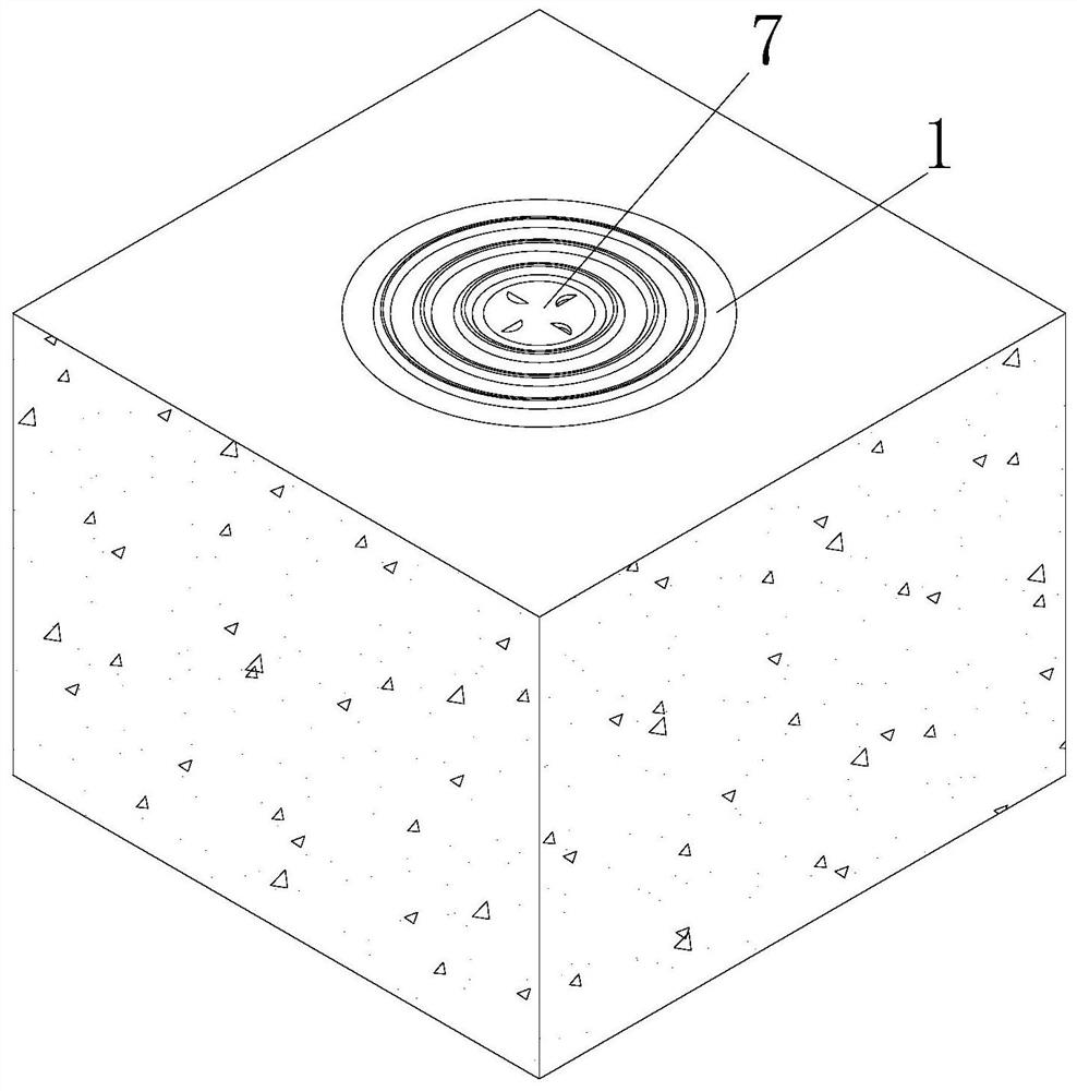
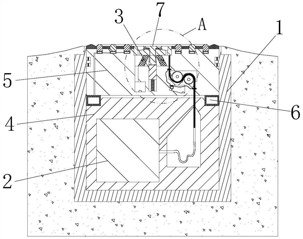
[0031] see Figure 1-6 As shown, a new energy vehicle charging device includes a fixed case 1, a power box 2 and a charging plug 3; the fixed case 1 is fixedly connected to the ground, and the top surface of the fixed case 1 is flush with the ground; the fixed case 1 is fixedly connected with a fixed block 4 near the bottom surface of the fixed shell 1; the inside of the fixed block 4 is fixedly connected with a power supply box 2; the inside of the fixed shell 1 is slidably connected with a sliding block 5; a pressure bag 6 is firmly connected between the slider 5 and the fixed block 4; the top surface of the slider 5 is provided with an installation groove; the inside of the installation groove is provided with a charging plug 3; the charging plug 3 is fixedly connected with a protective plate 7; the surface of the protective plate 7 is provided with uniformly arranged grooves; a charging line 8 is connected between the charging plug 3 and the power box 2; the top of the sli...
Embodiment 2
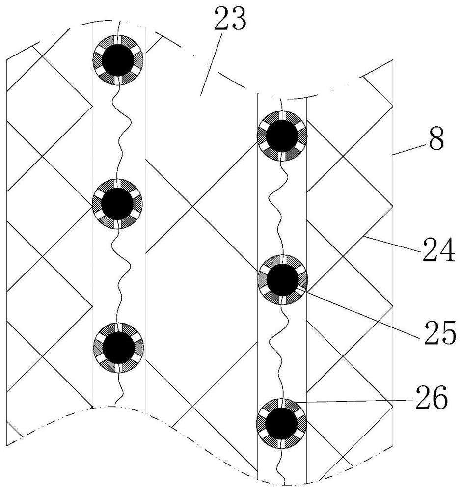
[0041] see Figure 7 As shown, an adjustment cavity is provided between the power supply box 2 and the rollers; the inside of the adjustment cavity is rotatably connected to a reel 27, and the charging wire 8 is wound on the surface of the reel 27; the inside of the fixed block 4 is fixedly connected There is a rotating shaft 28, and the surface of the rotating shaft 28 is wound with a first elastic piece 29, and the end of the first elastic piece 29 is fixedly connected with the reel 27; the end surface of the reel 27 is fixedly connected with the limit post 30; The inside of 4 is provided with a limit groove at the position of the limit post 30; the inside of the limit groove is slidingly connected to the limit block 31; the second spring is fixedly connected between the limit block 31 and the bottom of the limit groove 32; the side surface of the limit block 31 away from the second spring 32 is fixedly connected to the limit bag 33, and the limit bag 33 and the control bag ...
PUM
 Abstract
Description
Claims
Application Information
 - R&D Engineer
- R&D Manager
- IP Professional
- Industry Leading Data Capabilities
- Powerful AI technology
- Patent DNA Extraction
Browse by: Latest US Patents, China's latest patents, Technical Efficacy Thesaurus, Application Domain, Technology Topic.
© 2024 PatSnap. All rights reserved.Legal|Privacy policy|Modern Slavery Act Transparency Statement|Sitemap