Paper product rotary printing mechanism for finished product packaging

A printing mechanism and packaging technology, applied to printing machines, general parts of printing machinery, printing, etc., can solve the problems of long time consumption, low work efficiency, blurred fonts, etc., to improve the gas circulation effect, improve the heating effect, increase The effect of exposure

Inactive Publication Date: 2021-07-27
峨眉山佳洁纸制品有限责任公司
View PDF10 Cites 0 Cited by
  • Summary
  • Abstract
  • Description
  • Claims
  • Application Information

AI Technical Summary

Problems solved by technology

[0003] After the current paper products are rotated and printed, there is a problem of carrying the printing ink when it is not dry, which leads to blurred printing on the surface of the paper products, and it takes a long time to dry normally, which is not conducive to the mass printing of paper products for finished packaging. The work efficiency is low, and the current factory mostly adopts the method of air drying to accelerate the drying effect, but the gas flow rate is too large, which will cause the printing ink to blow off and the font to appear blurred

Method used


Image

  • Paper product rotary printing mechanism for finished product packaging
  • Paper product rotary printing mechanism for finished product packaging
  • Paper product rotary printing mechanism for finished product packaging

Examples


Embodiment 1

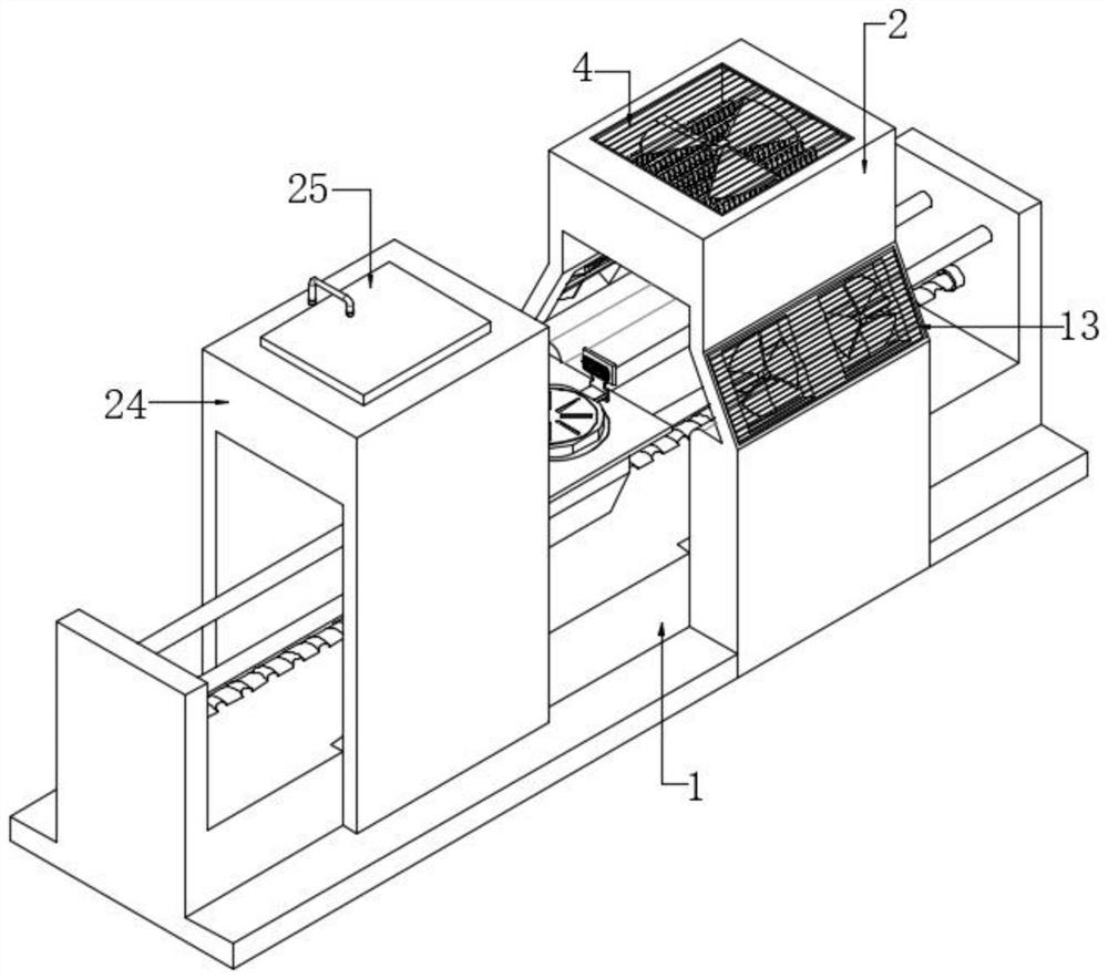
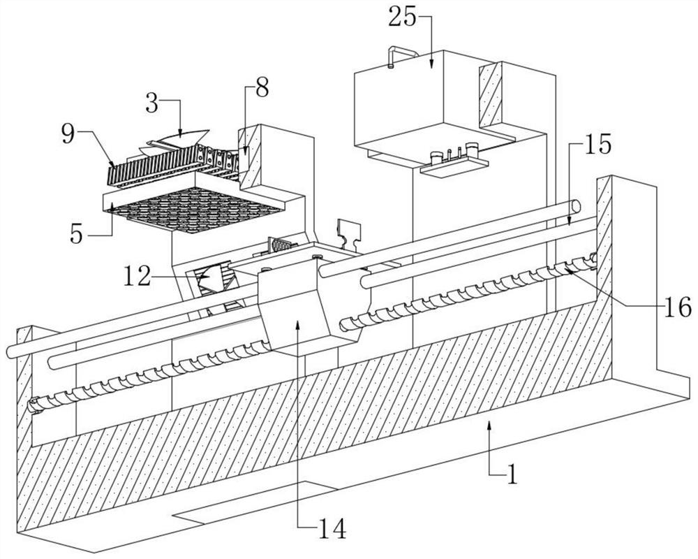
[0027] refer to Figure 1-5 , a paper product rotary printing mechanism for finished product packaging, comprising a base 1, the upper outer wall of the base 1 is connected with a drying box 2 by bolts, and a support rod is connected between the inner walls of the two sides of the drying box 2 by bolts, and the support rod One side of the outer wall is connected with a suction fan 3 by bolts, the upper outer wall of the drying box 2 is provided with a square groove, and the inner wall of the square groove is connected with a dust-proof net 4 by bolts, and a wind resistance box 5 is arranged below the suction fan 3, and the wind resistance The outer wall of the box 5 and the inner wall of the drying box 2 are connected by bolts, and the wind resistance box 5 is provided with a plurality of circular holes, and the inner walls of the plurality of circular holes are all rotatably connected with a drum 6, and the inner wall of the drum 6 is connected by bolts. A windshield 7, the w...

Embodiment 2

[0036] refer to Figure 6 , a paper product rotary printing mechanism for finished product packaging. Compared with Embodiment 1, this embodiment also includes a bottom plate 26 under the base 1, and the upper outer wall of the bottom plate 26 and the lower outer wall of the base 1 are provided with four a square slot, and a damper 27 is connected by bolts between the upper and lower square slots.

[0037] During use, the device will vibrate due to the rotation of the lead screw 16 and the work of the internal motor during use, and the damper 27 can slow down the vibration of the device, avoiding noise and excessive vibration that affect the normal operation of the device.


PUM


Abstract

The invention belongs to the technical field of printing equipment, particularly relates to a paper product rotary printing mechanism for finished product packaging, and provides the following scheme for solving the problems that after rotary printing of existing paper products, a factory mostly adopts an air drying manner to accelerate the drying effect, but printing ink is blown away and fonts are fuzzy due to the fact that the gas flow rate is too large. The mechanism comprises a base, a drying box is fixedly connected to the outer wall of the upper side of the base, a supporting rod is fixedly connected between the inner walls of the two sides of the drying box, and a suction fan is fixedly connected to the outer wall of one side of the supporting rod. A square groove is formed in the outer wall of the upper side of the drying box. The surface of a printed paper product is blown and dried after being heated by external air, rapid air drying of printing ink is accelerated, flowing airflow is blown to alternate air blocking pieces to drive a roller to rotate, the overall kinetic energy of the flowing airflow is reduced, and the situation that the flowing speed of the airflow sucked into the drying box is too large, the printing ink is directly air-dried, consequently, the printing ink is blown away, and printing is fuzzy is avoided.

Description

technical field [0001] The invention relates to the technical field of printing equipment, in particular to a paper product rotary printing mechanism for finished product packaging. Background technique [0002] Paper product printing is to first make the printing plate of the text and image to be printed, install it on the printing machine, and then apply the ink to the place where the text and image are on the printing plate manually or by the printing machine, and then directly or indirectly transfer to the printing plate. The surface of paper products needs to be printed to explain the information of the items in the paper product packaging, which is convenient for sorting and transportation. [0003] After the current paper products are rotated and printed, there is a problem of carrying the printing ink when it is not dry, which leads to blurred printing on the surface of the paper products, and it takes a long time to dry normally, which is not conducive to the mass p...

Claims


Application Information

Patent Timeline
Patent Type & Authority Applications(China)
IPC IPC(8): B41F23/04F16F15/08
CPCB41F23/0466F16F15/085
Inventor 宋浩仁
Owner 峨眉山佳洁纸制品有限责任公司
Why Eureka
Try Eureka