
Turning clamp structure for thin sheet parts with deflection and using method of turning clamp structure

A technology of parts and thin slices, which is applied in the field of lathe fixture structure with disturbance, can solve the problems of uneven positioning surface, difficult clamping, difficult positioning, etc., and achieve the advantages of increased overall strength, high production efficiency and low production cost. Effect

Active Publication Date: 2021-07-27
GUIZHOU HONGLIN MACHINERY
View PDF14 Cites 1 Cited by
  • Summary
  • Abstract
  • Description
  • Claims
  • Application Information

AI Technical Summary

Problems solved by technology

The reasons are: (1) The product is disturbed, the positioning surface is uneven, and positioning is difficult
(2) The product is a special-shaped piece, and it is difficult to orientate
(3) The thickness of the product is only 1.5mm and it is easy to deform, so it is difficult to clamp
[0006] processing Outer circle size to When it comes to dimensioning, the conventional method is: (1) Use the clamping method of three-jaw supporting the inner hole of the part to process the outer circle, but the existing situation is that the inner hole is too small, and there is no way to support the inner hole Dimensions to process the outer circle, can not be achieved
(2) A general three-jaw chuck is used to clamp the outer circle for processing, but the wall thickness of the part is too thin, its thickness is only 1.5mm and there is a disturbance, the part has no clamping part, and it is easy to deform during the turning process, which cannot be realized Processing of clamping outer circle

Method used


Image

  • Turning clamp structure for thin sheet parts with deflection and using method of turning clamp structure
  • Turning clamp structure for thin sheet parts with deflection and using method of turning clamp structure
  • Turning clamp structure for thin sheet parts with deflection and using method of turning clamp structure

Examples


Embodiment Construction

[0032] The present invention will be further described below in conjunction with the accompanying drawings and embodiments, but not as a basis for limiting the present invention.

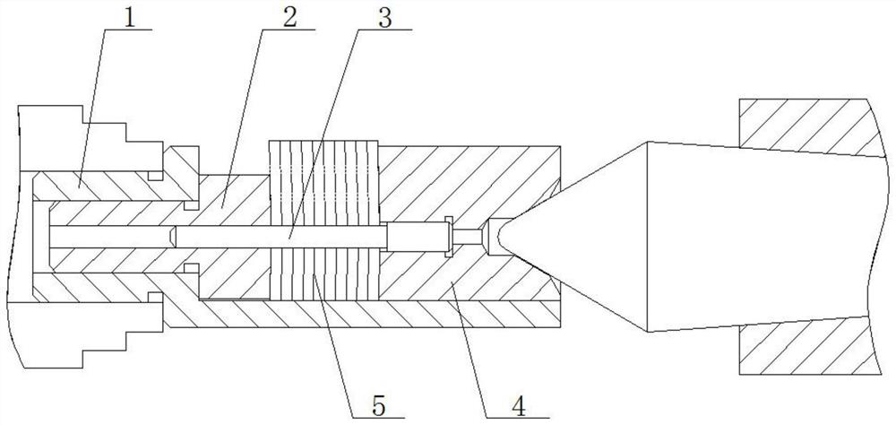
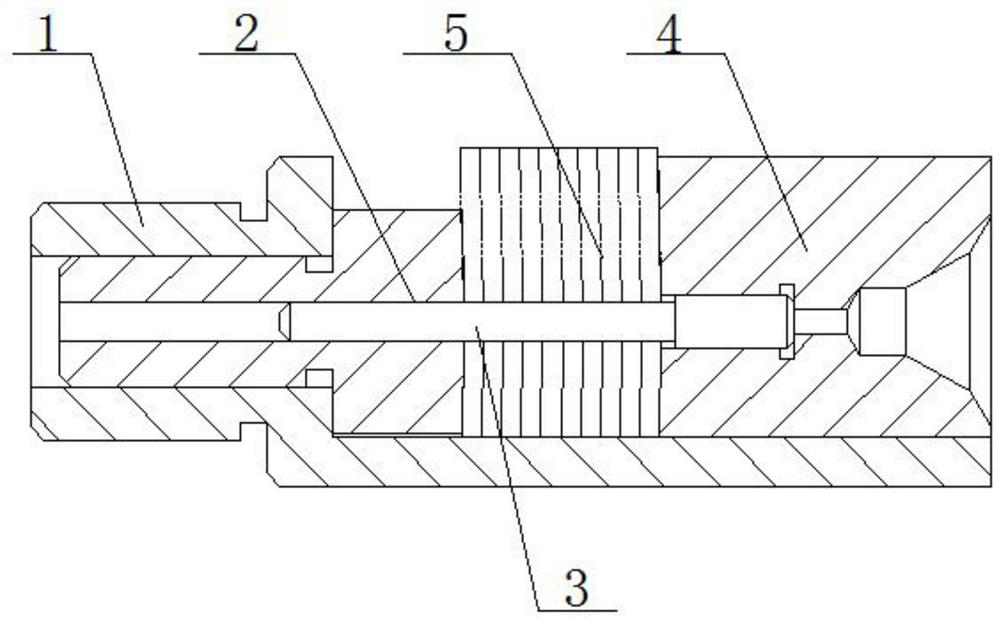
[0033] Embodiment of the present invention: a laminar part turning fixture structure with disturbance, as attached Figure 1-9As shown, it includes a clamping rod 1, the lower end of one side of the clamping rod 1 is provided with a horizontally protruding support plate, and the inside of the clamping rod 1 is provided with a positioning bush fixing hole along its length direction, and the positioning bush fixing hole is It is used to fix the positioning bush 2. There is a positioning mandrel penetration hole inside the positioning bushing 2, which is used to penetrate the positioning mandrel 3. It also includes a pressing block 4 placed on the other end of the support plate. The pressing block 4 One end facing the positioning bush 2 is provided with a positioning mandrel fixing hole, the tail of th...


PUM

PropertyMeasurementUnit
thicknessaaaaaaaaaa
thicknessaaaaaaaaaa

Abstract

The invention discloses a turning clamp structure for thin sheet parts with deflection. The turning clamp structure for the thin sheet parts with deflection comprises a clamping rod; a supporting plate horizontally extending out is arranged at the lower end of one side of the clamping rod; a positioning bush fixing hole is formed in the clamping rod in the length direction of the clamping rod; a positioning bush is fixed in the positioning bush fixing hole; a positioning mandrel penetrating hole is formed in the positioning bush; the device further comprises a pressing block placed at the other end of the supporting plate; a positioning mandrel fixing hole is formed in the end, facing the positioning bush, of the pressing block; the tail of a positioning mandrel is fixed in the positioning mandrel fixing hole; after a plurality of thin sheet parts overlapped in the same direction penetrate into a shaft body of the positioning mandrel, the head end of the positioning mandrel extends into the positioning mandrel penetrating hole, wherein the end faces, in contact with the thin sheet part, of the positioning bush and the pressing block are of the same structure as the contact face of the thin sheet part. The clamp structure solves the problems of difficult positioning, difficult orientation, difficult clamping, difficult pressing and the like when the excircle of the thin sheet part with deflection is turned.

Description

technical field [0001] The invention relates to a laminar part lathe tool fixture structure and its use method, in particular to a laminar laminar lathe lathe work fixture structure and its use method. Background technique [0002] Machine tool fixture design is an important part of process equipment design. In the entire machining process, in addition to clamping and fixing the processed parts, the fixture is also required to ensure the tolerance accuracy of the processed parts and improve the processing productivity. [0003] In the field of mechanical production and processing, it is often necessary to process various thin sheet parts. Such parts are small in size, thin in thickness, and have poor rigidity. Processing quality, especially thin sheet parts with disturbance, how to quickly and efficiently clamp them to various processing equipment to process qualified products is an urgent problem to be solved. In our company's products, there is a special-shaped sheet part...

Claims


Application Information

Patent Timeline
Patent Type & Authority Applications(China)
IPC IPC(8): B23Q3/00B23B5/00
CPCB23Q3/00B23B5/00
Inventor 黄小梅刘振伟刘娅菲何林美周可平罗亮
Owner GUIZHOU HONGLIN MACHINERY
Learn More