Portable manual surgical robot
A portable and robotic technology, applied in the field of medical devices, can solve the problems of inability to reach the target organization from multiple angles, high price, inability to popularize and realize commercial operation, etc., to improve portability and popularity, reduce volume and use cost. Effect
- Summary
- Abstract
- Description
- Claims
- Application Information
AI Technical Summary
Problems solved by technology
Method used
Image
Examples
Embodiment 1
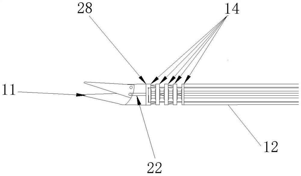
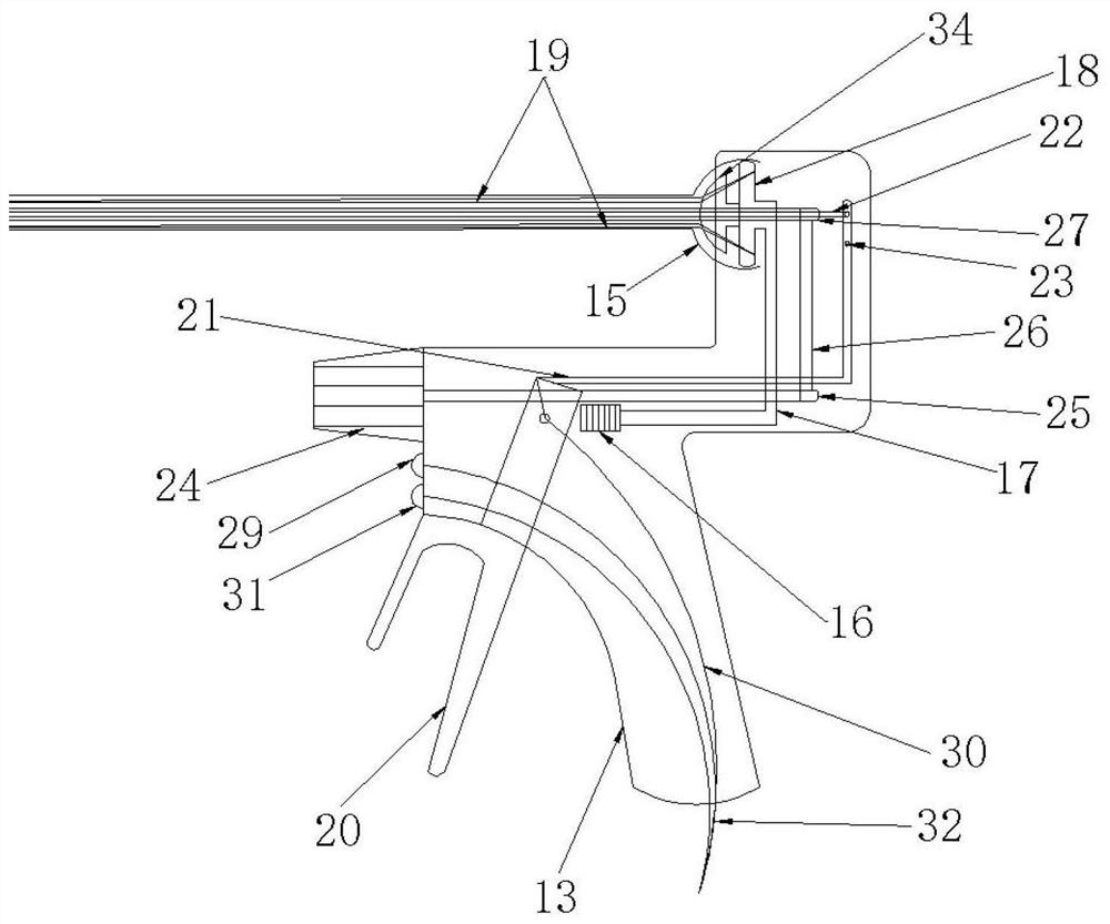
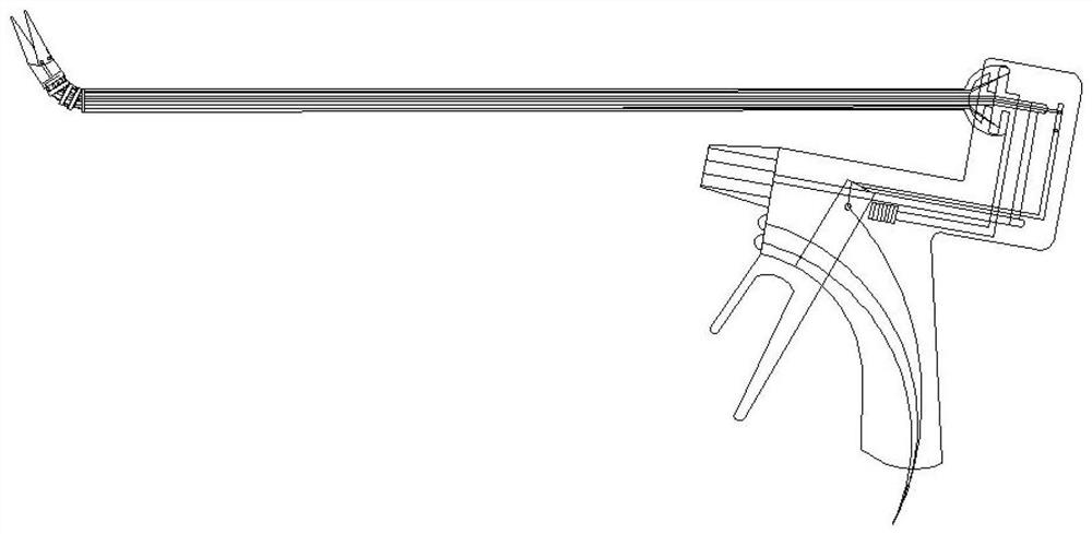
[0027] like figure 1 and figure 2 As shown, the portable manual surgical robot of the present embodiment includes: the cutter head 11, the shaft 12, and the handle 13,
[0028] The cutter head is connected to the front end of the shaft 12 through the curved joint 14.
[0029] The joint 15 is a hollow hemispherical, located at the joint of the shaft and the handle, the front end of the joint 15 is integrated with the shaft, and the housing of the rear end and the handle 13 rotates through the spherical surface.
[0030] The joint lock switch 16 is disposed on the side of the upper segment of the handle 13, and the position of the thumb can be turned to the handle when the handle is holding the handle.
[0031] The joint locking drive shaft 17 is a L-shaped, the front end is fixed to the joint lock switch 16, and the tail end is fixed to the joint lock ring 18.
[0032] The joint lock ring 18 is located in a spherical space within the joint 15. When the joint lock switch 16 is moved...
Embodiment 2
[0051] like Figure 5 As shown, the portable manual surgical robot of the present embodiment changes the structure of the cutting and rotation of the cutter head 11 on the basis of the first example.
[0052] The cutter rotary hollow shaft 2 is extended down to the cutter head opening and closing lever 20, and the cutter head opening and closing the steel rope 22 is also connected to the cutter head opening and closing lever 20 in the cutter head. The pressing tool head opening and closing lever 20 can drive the cutter head opening and closing shaft 21 and the cutter head in the cutter head in the axial shaft 27, so that the distal cutter head 11 performs opening and closing motion.
[0053] like Figure 5 As shown, a set of tool head rotation transmission gear 33 is mounted at the cutter head rotation shaft 27 and the cutter head rotation drive shaft 25, respectively, located at the position of the cutter head rotation drive shaft and the rotary air mandrel intersection, and meshin...
Embodiment 3
[0055] The portable manual surgical robot of the present embodiment changes the joint position and the joint fixing structure on the basis of the second embodiment.
[0056] like Image 6 As shown, the joint 15 is movable rearward, and the joint is located above the manipulator's wrist joint, and corresponds to the longitudinal position of the manipulator wrist, so that the wrist joint movement is more stable and the distal can be more stable and can eliminate the first example. And the wrist joint caused by the joint 15 in the second secondary structure is curved up and down, and the shake of the shaft and the cutter head 11 improves stability and precision.
[0057] The joint lock drive shaft 17 is shortened so that the force of the joint lock ring 18 is driven to lock the joint lock ring 18 to lock the joint of the joint, and the structure is simpler.
PUM
 Abstract
Description
Claims
Application Information
 - R&D Engineer
- R&D Manager
- IP Professional
- Industry Leading Data Capabilities
- Powerful AI technology
- Patent DNA Extraction
Browse by: Latest US Patents, China's latest patents, Technical Efficacy Thesaurus, Application Domain, Technology Topic, Popular Technical Reports.
© 2024 PatSnap. All rights reserved.Legal|Privacy policy|Modern Slavery Act Transparency Statement|Sitemap|About US| Contact US: help@patsnap.com


