Permanent magnet motor with motor cover easy to replace

A permanent magnet motor, motor cover technology, applied in electrical components, electromechanical devices, electric components, etc., can solve the problems of dust extrusion and hardening, and the rotation of the shaft is blocked.

Inactive Publication Date: 2021-07-23
TAIZHOU LIKE TECH CO LTD
View PDF8 Cites 0 Cited by
  • Summary
  • Abstract
  • Description
  • Claims
  • Application Information

AI Technical Summary

Problems solved by technology

[0003] Due to the convenient replacement of the motor installed on outdoor mechanical equipment, the cover-type permanent magnet motor needs to be in contact with the outside world for a long time, especially when the drilling machine is drilling the ground, it is prone to generate a lot of dust, so that fine dust can easily enter the shaft and Inside the gap between the motor covers, long-term accumulation will easily cause dust to be squeezed and hardened by the rotation of the shaft, which will hinder the rotation of the shaft

Method used


Image

  • Permanent magnet motor with motor cover easy to replace
  • Permanent magnet motor with motor cover easy to replace
  • Permanent magnet motor with motor cover easy to replace

Examples


Embodiment 1

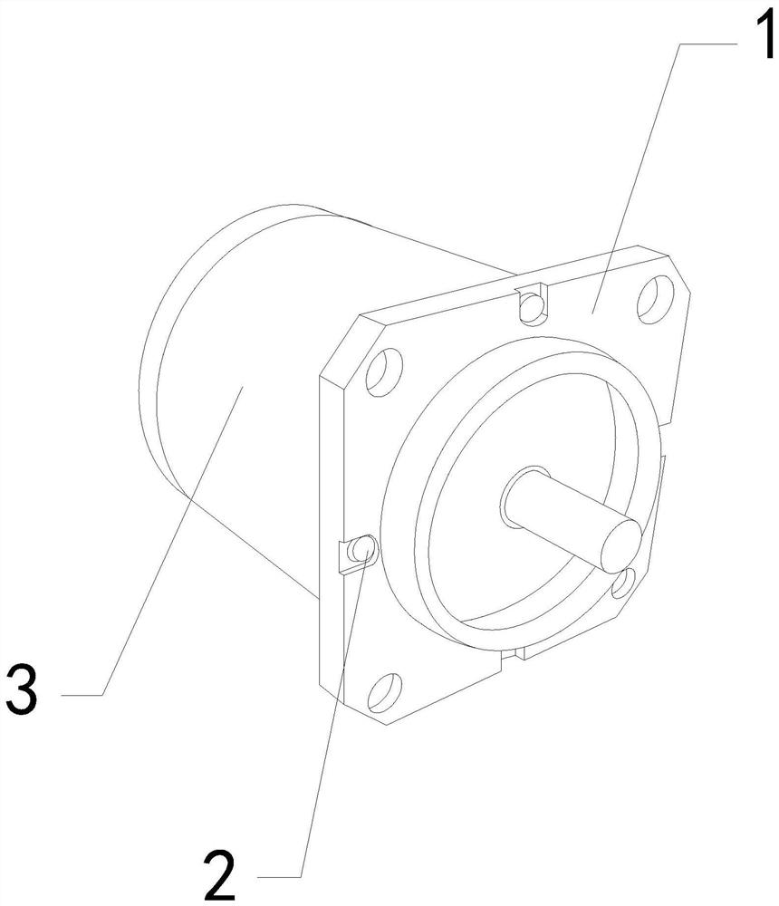
[0026] For example figure 1 -example Figure 5 Shown:

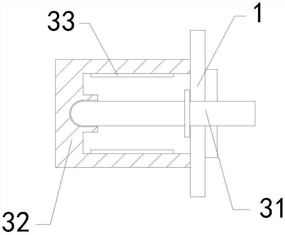
[0027] The present invention provides a permanent magnet motor that is easy to replace the motor cover. Its structure includes a motor cover 1, a fixing screw 2, and a motor 3. The fixing screw 2 is screwed to the motor cover 1, and the motor 3 is integrated with the motor cover 1. The motor 3 includes a rotating shaft 31, a casing 32, and a suction block 33, the rotating shaft 31 is movably engaged with the casing 32, and the suction block 33 is installed on the inner wall of the casing 32.

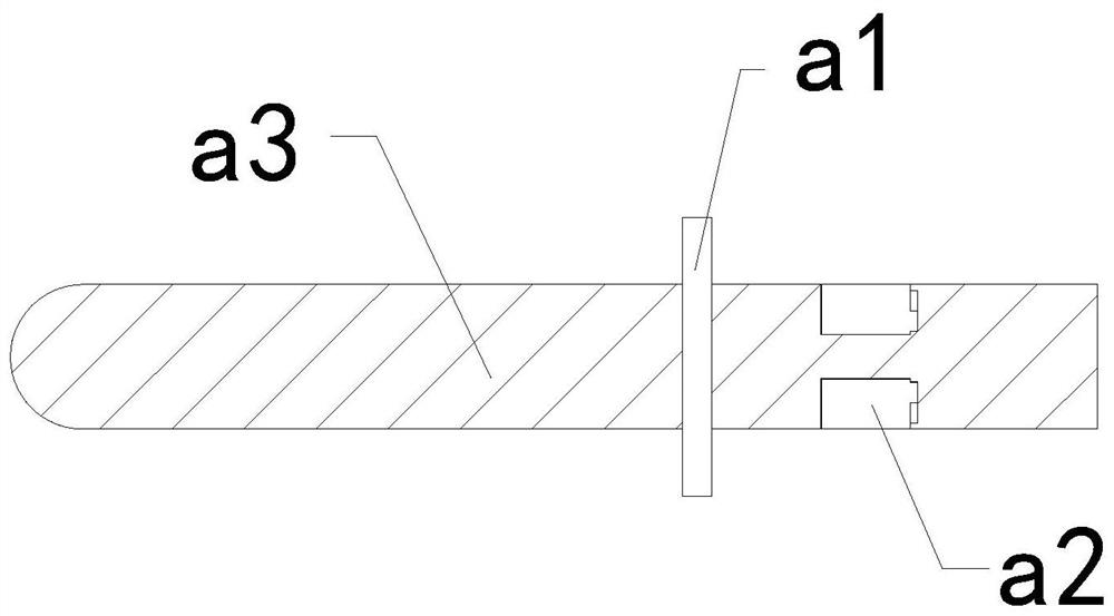
[0028] Wherein, the rotating shaft 31 includes a fixed plate a1, an overhanging block a2, and a rotating rod a3. The extending block a2 is movably engaged with the rotating rod a3. The rotating rod a3 and the fixing plate a1 are of an integrated structure. There are two overhanging blocks a2, and they are evenly distributed symmetrically on the rotating rod a3. The throwing force generated by the rotation of the mechanism can make...

Embodiment 2

[0034] For example Image 6 -example Figure 8 Shown:

[0035] Wherein, the contact reducing groove b1 includes a protruding frame b11, a middle solid block b12, and a frame body b13. In connection with each other, the extension frame b11 can be extended outward through the inertial force generated by the extension of the mechanism, so that the extension frame b11 can bounce off the dust layer inside it.

[0036] Wherein, the extension frame b11 includes an oil-absorbing block c1, a plate c2, and an air-drying mechanism c3, the oil-absorbing block c1 is embedded in the inner side of the plate c2, and the air-drying mechanism c3 is installed between the oil-absorbing block c1 and the plate c2, The oil-absorbing block c1 is made of corrosion-resistant polyether sponge, and the lubricating oil can be absorbed by the oil-absorbing block c1.

[0037] Wherein, the air-drying mechanism c3 includes a rebound bar c31, an exhaust chamber c32, a swing plate c33, and an outer ring c34....


PUM


Abstract

The invention discloses a permanent magnet motor with a motor cover easy to replace. The permanent magnet motor structurally comprises the motor cover, a fixing screw and a motor, wherein the fixing screw is in threaded connection with the motor cover, the motor and the motor cover are of an integrated structure, and an outward extending block can extend outwards along a rotating rod through throwing force generated by rotation of a rotating shaft on the motor, so that the outward extending block can shield the front end of the gap between the rotating rod and the motor cover; by means of the whole process, dust entering the space between the rotating shaft and the motor cover can be blocked, and by means of inertia force generated when the contact plate extends outwards, the extending frame can extend outwards along the middle fixing block, and lubricating oil in a touch reducing groove can be absorbed through an oil absorption block, so the extending frame can shake off dust when extending outwards, and the situation that the dust in the touch reducing groove is soaked by the lubricating oil, and consequently the dust stays in the touch reducing groove and is difficult to remove is effectively avoided.

Description

technical field [0001] The invention relates to the field of motors, in particular to a permanent magnet motor which is easy to replace a motor cover. Background technique [0002] Convenient replacement of the motor The cover-type permanent magnet motor is mainly used to drive mechanical equipment. After the rotating shaft is energized, the permanent magnet inside the motor can rotate at a high speed, so that the mechanical equipment can be driven to run. Based on the above description, the inventor found that , the existing permanent magnet motor that is easy to replace the motor cover mainly has the following deficiencies, for example: [0003] Due to the convenient replacement of the motor installed on outdoor mechanical equipment, the cover-type permanent magnet motor needs to be in contact with the outside world for a long time, especially when the drilling machine is drilling the ground, it is prone to generate a lot of dust, so that fine dust can easily enter the sha...

Claims


Application Information

Patent Timeline
IPC IPC(8): H02K5/124H02K5/10
CPCH02K5/124H02K5/10
Inventor 罗正权
Owner TAIZHOU LIKE TECH CO LTD
Why Eureka
Try Eureka