Combined transmission gear convenient to disassemble and assemble

A transmission gear, combined technology, applied in the directions of portable lifting devices, belts/chains/gears, hoisting devices, etc., can solve the problems of increasing the use cost of gears, prolonging the maintenance time, increasing the maintenance cost, etc., and improving the efficiency of replacement. , the effect of reducing labor intensity and reducing maintenance costs

Inactive Publication Date: 2021-07-23
陈金萍
View PDF0 Cites 0 Cited by
  • Summary
  • Abstract
  • Description
  • Claims
  • Application Information

AI Technical Summary

Problems solved by technology

[0004] The object of the present invention is to provide a combined transmission gear that is easy to assemble and disassemble. Through the first annular groove, the first internal meshing mechanism, the second internal meshing , The design of the second external meshing mechanism, arc-shaped mounting hole, threaded rod and two-way threaded rod solves the problem that the existing one-piece gear structure is fixed and cannot be disassembled. When the gear fails, only the whole gear can be replaced, which greatly increases The maintenance cost is reduced, and the gear needs to be repositioned during the replacement process, which is cumbersome and greatly prolongs the maintenance time. The existing integrated gears have fixed models and specifications and are used as a set. When other specifications of gears are required, only The replacement of new gears greatly increases the cost of using the gears

Method used


Image

  • Combined transmission gear convenient to disassemble and assemble
  • Combined transmission gear convenient to disassemble and assemble
  • Combined transmission gear convenient to disassemble and assemble

Examples


Embodiment Construction

[0048] The following will clearly and completely describe the technical solutions in the embodiments of the present invention with reference to the accompanying drawings in the embodiments of the present invention. Obviously, the described embodiments are only some, not all, embodiments of the present invention. Based on the embodiments of the present invention, all other embodiments obtained by persons of ordinary skill in the art without creative efforts fall within the protection scope of the present invention.

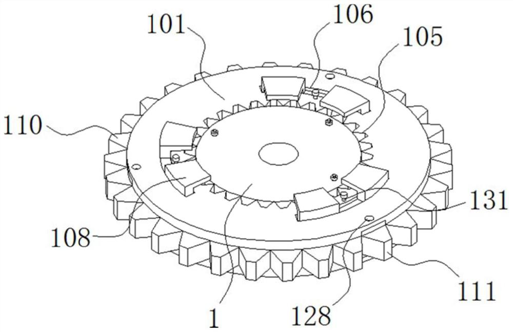
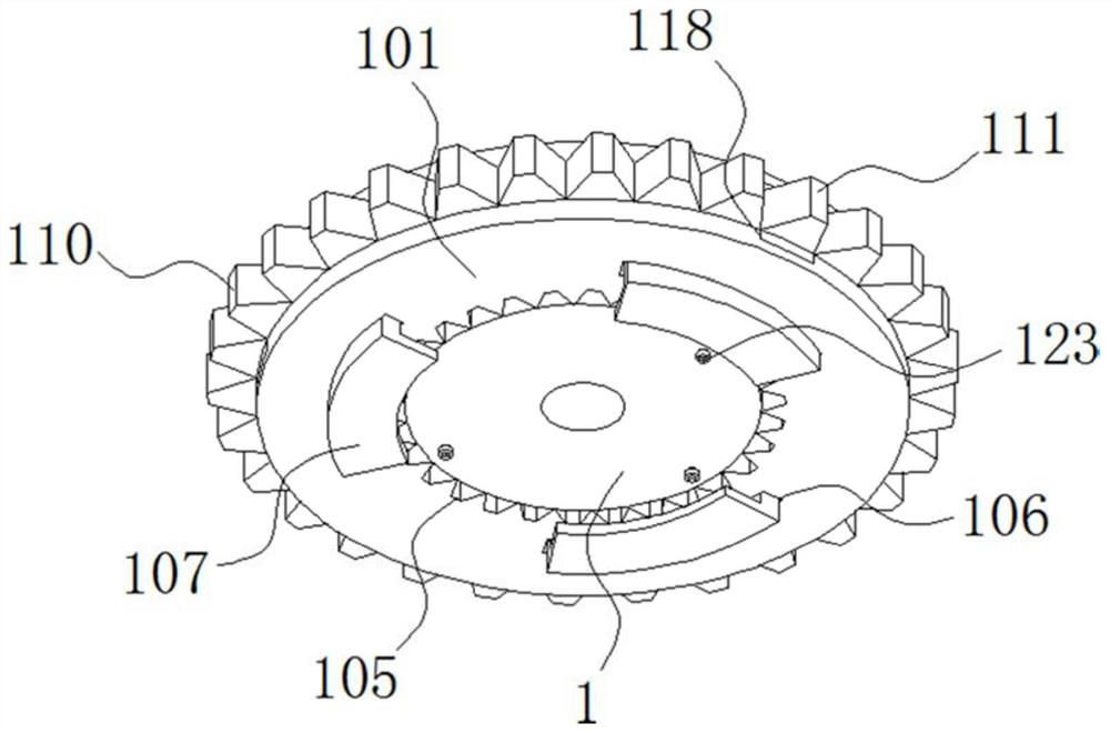
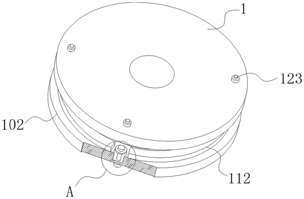
[0049] see Figure 1-10 , the present invention is a combined transmission gear that is easy to assemble and disassemble, including an internal tooth mounting plate 1 and an external tooth mounting ring 101;

[0050] A first annular groove 102 is opened on the side of the inner tooth mounting plate 1; inside the first annular groove 102, a number of first internal meshing mechanisms 103 and second internal meshing mechanisms 104 are slidably fitted; one side of the...


PUM


Abstract

The invention discloses a combined transmission gear convenient to disassemble and assemble, and relates to the technical field of gears. The combined transmission gear comprises an inner tooth mounting plate and an outer tooth mounting ring; a first inner meshing mechanism and a second inner meshing mechanism are arranged in a first annular groove in a sliding fit mode; the inner wall of a tooth-shaped clamping groove is in clearance fit with the circumferential side surface of the first inner meshing mechanism and the circumferential side surface of the second inner meshing mechanism; one side surface of the inner tooth mounting plate is tightly attached to one inner side surface of a first fastening clamping plate; the opposite side surface of the inner tooth mounting plate is tightly attached to one inner side surface of a second fastening clamping plate; a first outer meshing mechanism and a second outer meshing mechanism are arranged in a second annular groove in a sliding fit mode. Through design of the first annular groove, the second annular groove, the first inner meshing mechanism, the second inner meshing mechanism, the first outer meshing mechanism and the second outer meshing mechanism, resource waste is effectively avoided, the maintenance cost and the labor intensity of maintenance personnel are greatly reduced, and the maintenance time is greatly shortened.

Description

technical field [0001] The invention belongs to the technical field of gears, in particular to a combined transmission gear that is easy to assemble and disassemble. Background technique [0002] Gears are wheel-shaped mechanical parts that transmit torque by the meshing of teeth. The gear can achieve functions such as changing the speed and torque, changing the direction of motion, and changing the form of motion through other toothed mechanical parts (such as another gear, rack, and worm). Due to the advantages of high transmission efficiency, accurate transmission ratio, and large power range, gear mechanisms are widely used in industrial products, and their design and manufacturing levels can directly affect the quality of industrial products. Gears are the main basic transmission components in the automotive industry, and the quality of the gears directly affects the noise, stability and service life of the car. As the main part of the car transmission system, the car...

Claims


Application Information

Patent Timeline
Patent Type & Authority Applications(China)
IPC IPC(8): F16H55/12F16H55/17
CPCF16H55/12F16H55/17
Inventor 陈金萍
Owner 陈金萍
Why Eureka
Try Eureka