
Welding device suitable for batch machining of steel bar truss floor support plates

A steel truss, batch processing technology, applied in the direction of auxiliary devices, welding equipment, welding equipment, etc., can solve the problems of increased labor output, low production efficiency of steel truss floor decks, and inability to weld multiple steel trusses, etc., to reduce The output of labor force, the realization of welding automation, and the effect of increasing practicability

Inactive Publication Date: 2021-07-23
徐州中煤汉泰建筑工业化有限公司
View PDF12 Cites 3 Cited by
  • Summary
  • Abstract
  • Description
  • Claims
  • Application Information

AI Technical Summary

Problems solved by technology

[0004] The purpose of the present invention is to provide a welding device suitable for batch processing of steel truss floor decks, so as to solve the problem that multiple steel bar trusses cannot be welded at the same time when the steel bar truss floor decks proposed in the background technology are processed, resulting in The production efficiency of the truss floor deck is low, and there is no handling equipment after the production is completed, which increases the output of labor force

Method used


Image

  • Welding device suitable for batch machining of steel bar truss floor support plates
  • Welding device suitable for batch machining of steel bar truss floor support plates
  • Welding device suitable for batch machining of steel bar truss floor support plates

Examples


Embodiment Construction

[0030] The following will clearly and completely describe the technical solutions in the embodiments of the present invention with reference to the accompanying drawings in the embodiments of the present invention. Obviously, the described embodiments are only some, not all, embodiments of the present invention. Based on the embodiments of the present invention, all other embodiments obtained by persons of ordinary skill in the art without making creative efforts belong to the protection scope of the present invention.

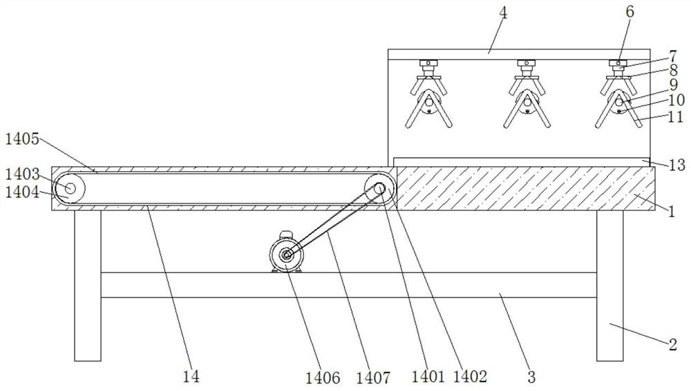
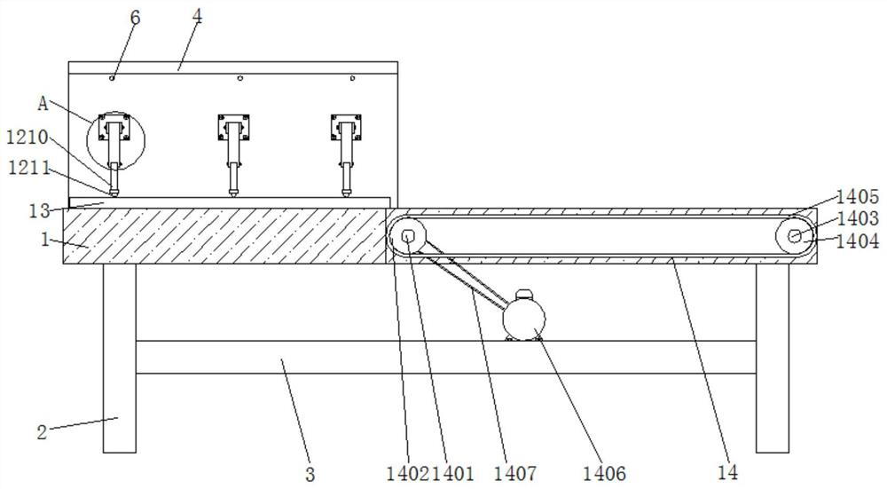
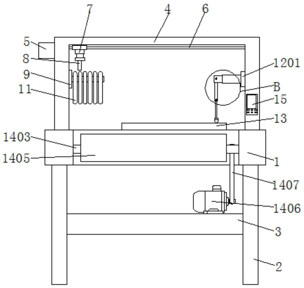
[0031] see Figure 1-6 , the present invention provides a technical solution: a welding device suitable for batch processing steel truss floor decks, according to figure 1 , figure 2 and image 3 As shown, the bottom of the workbench 1 is provided with support legs 2 on the left and right, and four support legs 2 are provided. The upper end of the rear outer wall is equipped with a first motor 5, and the output end of the first motor 5 runs through the bra...


PUM


Abstract

The invention discloses a welding device suitable for batch machining of steel bar truss floor support plates. The welding device comprises a workbench, a welding mechanism, a storage table and a conveying mechanism, supporting legs are arranged on the left side and the right side of the bottom of the workbench, a support is installed at the upper end of the right side of the workbench, a lead screw structure is installed at the upper end in the support, a clamping base is installed at the bottom of an electric telescopic rod, a fixing rod is arranged on the inner wall of the rear side of the support, the welding mechanism is installed on the inner wall of the front side of the support, the storage table is arranged at the upper end of the right side of the workbench, and the conveying mechanism is installed on the left side of the workbench. According to the welding device suitable for batch machining of the steel bar truss floor support plates, the welding mechanism is arranged, through matched use of a fixing base, a first supporting arm, a second supporting arm, a welding gun and a welding head, in the welding process of a steel bar truss, the welding gun does not need to be manually held for operation, meanwhile, the production efficiency of the steel bar truss floor support plates is improved, and welding automation is achieved.

Description

technical field [0001] The invention relates to the technical field of building material production equipment, in particular to a welding device suitable for batch processing of reinforced truss floor decks. Background technique [0002] Reinforced truss floor deck is a building product in which the reinforced steel bars in the floor are welded into reinforced trusses in the factory, and the reinforced trusses are fixedly connected with the bottom formwork to form the integration of the bottom formwork and the stressed steel bars. During construction, the reinforced truss floor deck is fixed between two load-bearing beams, and concrete is poured directly. The bottom formwork bears the gravity of the concrete, and the reinforced truss provides unsupported stiffness for the formwork. [0003] When the existing steel truss floor deck is processed, it is impossible to weld multiple steel trusses at the same time, resulting in low production efficiency of the steel truss floor de...

Claims


Application Information

Patent Timeline
Patent Type & Authority Applications(China)
IPC IPC(8): B23K31/02B23K37/00B23K37/02B23K37/04
CPCB23K31/02B23K37/00B23K37/0435B23K37/0252
Inventor 董晨朱新颖吴锋徐臣
Owner 徐州中煤汉泰建筑工业化有限公司
Learn More