
Automobile brake-by-wire system

A technology of automotive wires and controllers, applied in the direction of brakes, brake transmissions, vehicle components, etc., can solve the problems of reducing motor speed and power requirements, insufficient carrying capacity, motor stalling, etc., to improve carrying capacity and use Longevity, reduction of potential safety hazards, effects of size reduction

Inactive Publication Date: 2021-07-20
YANGZHOU WUHUNLONG ELECTRIC VEHICLES
View PDF8 Cites 2 Cited by
  • Summary
  • Abstract
  • Description
  • Claims
  • Application Information

AI Technical Summary

Problems solved by technology

[0005] In view of the above problems, the present invention provides an automobile brake-by-wire system, which replaces the vacuum booster in the traditional hydraulic brake system with a motor, thereby canceling the dependence on the vacuum degree of the engine; The problem of motor stalling occurs during braking; the use of planetary gear trains reduces the speed and power requirements of the motor; the planetary roller screw mechanism is used to replace the traditional rack and pinion mechanism and ball screw mechanism to effectively solve the problem of load-bearing Insufficient capacity and short lifespan

Method used


Image

  • Automobile brake-by-wire system
  • Automobile brake-by-wire system
  • Automobile brake-by-wire system

Examples


Embodiment Construction

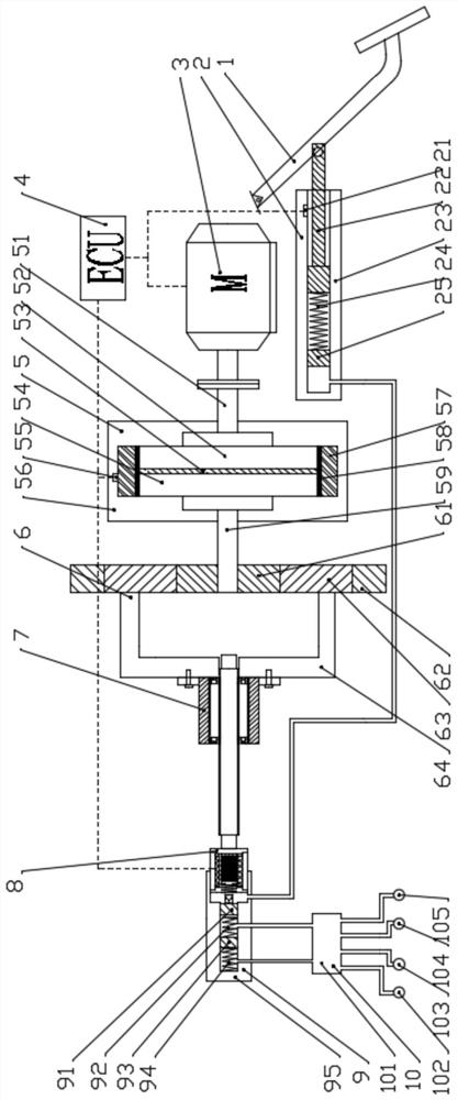
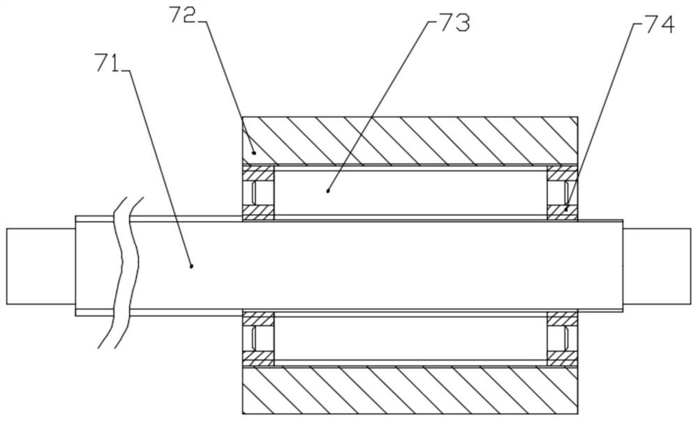
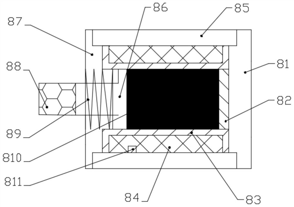
[0043] The automobile brake-by-wire system proposed by the present invention has a structure such as Figure 1-3 As shown, it includes brake pedal 1, pedal simulator 2, motor 3, controller 4, magneto-rheological clutch 5, planetary gear train 6, planetary roller screw mechanism 7, giant magnetostrictive drive mechanism 8, master cylinder 9. Brake actuator 10.

[0044] The magneto-rheological clutch 5 includes a clutch housing 56, an input shaft 51, a coil 57, a driving disc 52, a magneto-rheological fluid 53, a driven disc 54, an output shaft 59, and a first signal sensor 55; the clutch housing 56 and The motor housing (not shown in the figure) is fixedly connected, the input shaft 51 is connected with the transmission shaft of the motor 3 through a coupling, the driving disc 52 is connected with the input shaft 51 through a key, and the driving disc 52 and the driven disc 54 There is a certain amount of magnetorheological fluid 53 sealed between them. The output shaft 59 and...


PUM


Abstract

The invention discloses an automobile brake-by-wire system and belongs to the technical field of automobile brake systems. The system comprises a motor, a magnetorheological clutch, a planetary gear train, a planetary roller screw mechanism, a giant magnetostrictive driving mechanism, a main cylinder, a brake actuating mechanism, a brake pedal, a pedal simulator, a sensor and a controller. According to the brake system, a vacuum booster in a traditional hydraulic brake system is replaced by the motor, so that dependence on the vacuum degree of an engine is eliminated; the magneto-rheological clutch is used for effectively solving the problem of motor stalling during long-time braking; a planetary gear train is used for reducing speed and increasing torque, and the requirements for motor rotating speed and power are reduced; a planetary roller screw mechanism is used for replacing a traditional gear rack mechanism and a traditional ball screw mechanism, and the problems that the bearing capacity is insufficient and the service life is short are effectively solved. And the giant magnetostrictive driving mechanism is used as an auxiliary driving device, so that the system response time is prolonged, and meanwhile, the potential safety hazard caused by using a high-pressure energy accumulator is avoided.

Description

technical field [0001] The invention relates to the technical field of automobile braking systems, in particular to an automobile braking system by wire. Background technique [0002] The development of electric vehicles and smart vehicles has put forward new requirements for the braking system of vehicles. The traditional vacuum-assisted hydraulic braking system relies on the vacuum of the engine. When it is applied to an electric vehicle, an electric vacuum pump and a vacuum tank need to be installed, which increases the weight and energy consumption. At the same time, the vacuum-assisted hydraulic braking system is no longer suitable for the growing intelligent driving assistance systems, such as active collision avoidance and automatic parking. Therefore, it is necessary to design and develop a new braking system suitable for smart electric vehicles. [0003] Patent CN103010199A discloses a brake-by-wire system, which replaces the vacuum booster with a motor, and elimi...

Claims


Application Information

Patent Timeline
Patent Type & Authority Applications(China)
IPC IPC(8): B60T13/74
CPCB60T13/745B60T13/746
Inventor 徐惠民朱鹏范一兵耿国庆徐兴
Owner YANGZHOU WUHUNLONG ELECTRIC VEHICLES
Learn More