Method for avoiding stall caused by strong wind in vertical axis wind turbine
A wind turbine, vertical axis technology, applied in the direction of wind turbine components, wind engines, wind engines at right angles to the wind direction, etc., can solve the problems of broken, stalled blades, etc.
- Summary
- Abstract
- Description
- Claims
- Application Information
AI Technical Summary
Problems solved by technology
Method used
Image

Examples
Embodiment 1
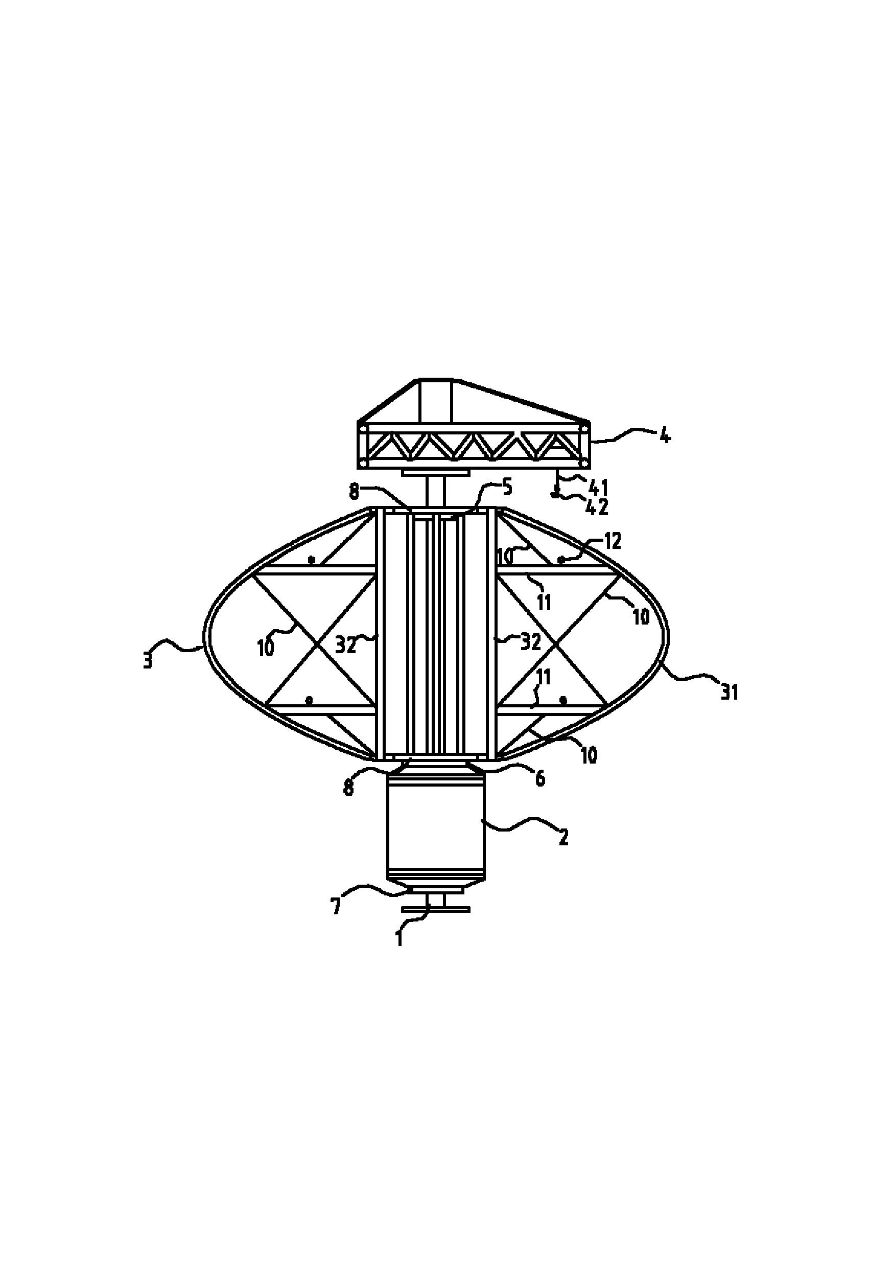
[0027] like figure 1 As shown, a device for avoiding a stall caused by strong wind of a vertical axis wind power generator includes a tower column 1 and more than one power generation unit arranged on the tower column 1. In this embodiment, only one A power generation unit, the power generation unit includes a Φ-shaped blade group, an outer rotor generator 2 and a crane 4 .
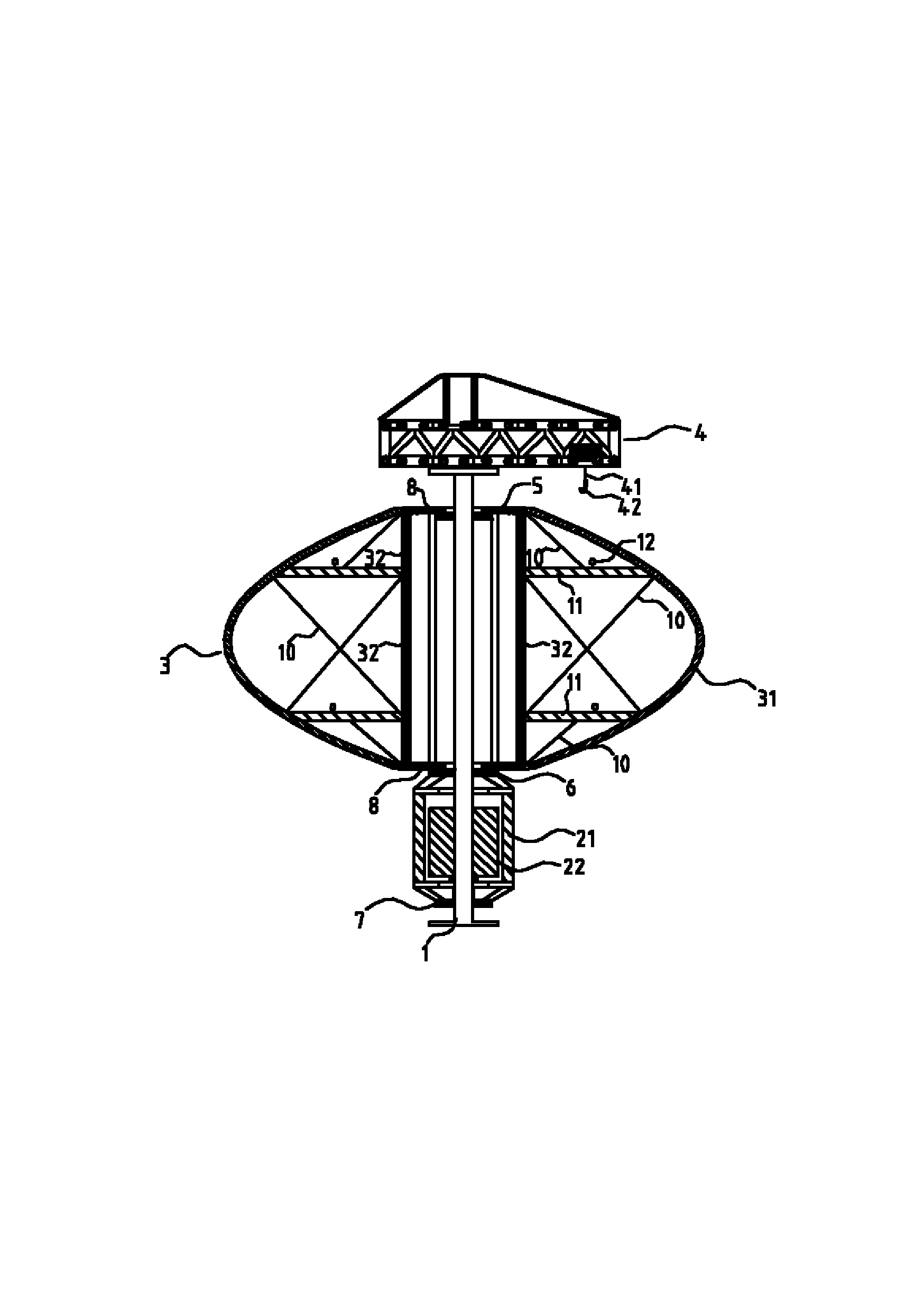
[0028] like figure 2 As shown, the upper end of the blade group is provided with a first bearing 5, the inner ring of the first bearing 5 is fixedly sleeved on the tower column 1, and the upper end of the blade group is connected with the outer ring of the first bearing 5; the lower end of the blade group is provided with a second Bearing 6, the inner ring of the second bearing 6 is fixedly sleeved on the tower column 1, the lower end of the blade group is connected with the outer ring of the second bearing 6, and the blade group is connected to the outer ring of the first bearing 5 and the second beari...
Embodiment 2
[0034] like Figure 4As shown, a device for avoiding a stall caused by strong wind of a vertical axis wind power generator includes a tower column 1 and more than one power generation unit arranged on the tower column 1. In this embodiment, the tower column 1 is only provided with two A power generation unit, which includes a Φ-shaped blade group, an outer rotor generator 2, and a crane 4.
[0035] like Figure 5 As shown, the upper end of the blade group is provided with a first bearing 5, the inner ring of the first bearing 5 is fixedly sleeved on the tower column 1, and the upper end of the blade group is connected with the outer ring of the first bearing 5; the lower end of the blade group is provided with a second Bearing 6, the inner ring of the second bearing 6 is fixedly sleeved on the tower column 1, the lower end of the blade group is connected with the outer ring of the second bearing 6, and the blade group is connected to the outer ring of the first bearing 5 and ...
Embodiment 3
[0041] like Figure 7 As shown, a device for avoiding a stall caused by strong wind of a vertical axis wind power generator includes a tower column 1 and more than one power generation unit arranged on the tower column 1. In this embodiment, the tower column 1 is only provided with two A power generation unit, which includes a Φ-shaped blade group, an outer rotor generator 2, and a crane 4.
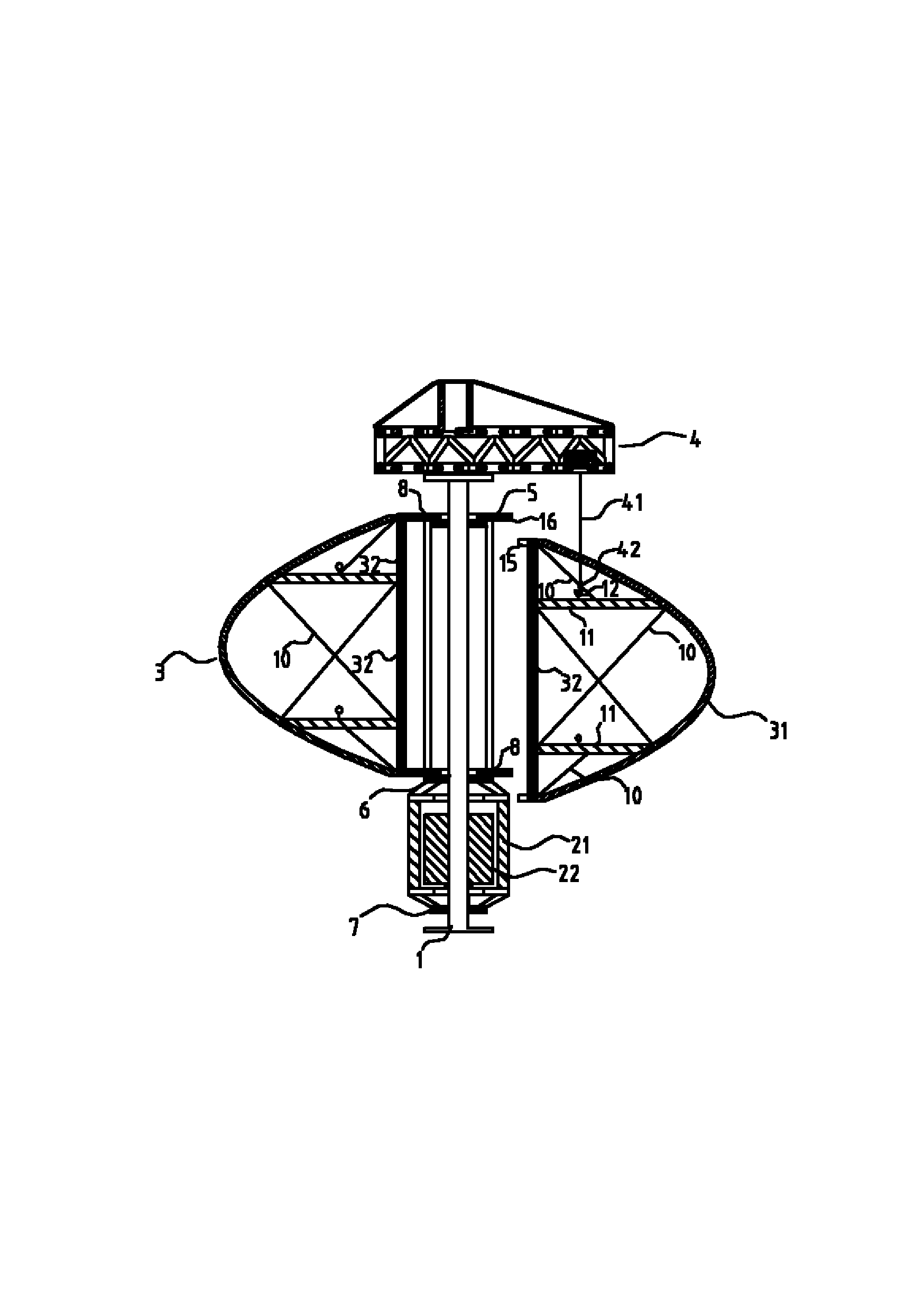
[0042] like Figure 8 As shown, the upper end of the blade group is provided with a first bearing 5, the inner ring of the first bearing 5 is fixedly sleeved on the tower column 1, and the upper end of the blade group is connected with the outer ring of the first bearing 5 through a connecting flange 8; the blade group The lower end is provided with a second upper bearing 6a, the inner ring of the second upper bearing 6a is fixedly sleeved on the tower column 1, the lower end of the blade group is connected with the outer ring of the second upper bearing 6a through the connecting flange ...
PUM
 Abstract
Description
Claims
Application Information
 - R&D
- Intellectual Property
- Life Sciences
- Materials
- Tech Scout
- Unparalleled Data Quality
- Higher Quality Content
- 60% Fewer Hallucinations
Browse by: Latest US Patents, China's latest patents, Technical Efficacy Thesaurus, Application Domain, Technology Topic, Popular Technical Reports.
© 2025 PatSnap. All rights reserved.Legal|Privacy policy|Modern Slavery Act Transparency Statement|Sitemap|About US| Contact US: help@patsnap.com