Starting or locked-rotor resisting method of direct-current brush motor

A brushed DC motor and motor rotor technology, which is applied to the starter of a single DC motor, the deceleration device of an AC motor, a motor generator/starter, etc. And other issues

Active Publication Date: 2021-07-16
SG MICRO
View PDF5 Cites 0 Cited by
  • Summary
  • Abstract
  • Description
  • Claims
  • Application Information

AI Technical Summary

Problems solved by technology

When the DC brush motor starts or stalls, because the winding coil is static, it needs to overcome the static torque of the winding coil to do work without the reverse electromotive force to suppress the winding coil current. At this time, the DC brush motor winding coil The starting current or locked-rotor current Iload is extremely large, at least 1.5 times the rated operating current, and it is very easy to trigger the overcurrent protection circuit of the H-bridge driver. Once the traditional overcurrent protection circuit of the H-bridge driver is triggered, it is easy to enter the above-mentioned The traditional over-current protection cycle, and the traditional over-current protection makes the DC brushed motor more difficult to start, if the selection of the H-bridge driver, the DC brushed motor model and the drag load do not match, the over-current detection of the traditional over-current protection circuit And the high resistance protection state will loop infinitely, that is, it has entered an infinite loop, and the brushed DC motor is blocked and cannot start by itself.

Method used


Image

  • Starting or locked-rotor resisting method of direct-current brush motor
  • Starting or locked-rotor resisting method of direct-current brush motor
  • Starting or locked-rotor resisting method of direct-current brush motor

Examples


Embodiment Construction

[0029] In order to facilitate the understanding of the present invention, the present invention will be described in more detail below in conjunction with the accompanying drawings and specific embodiments.

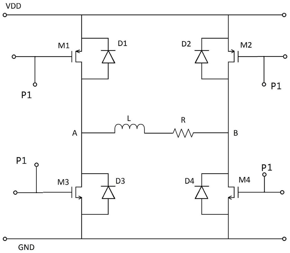
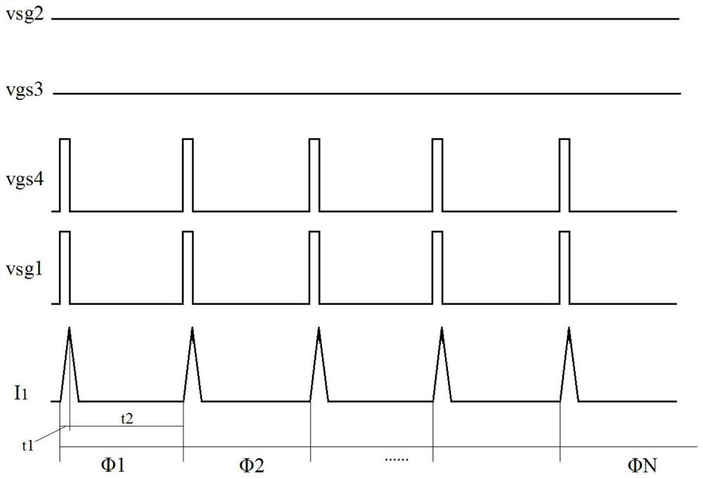
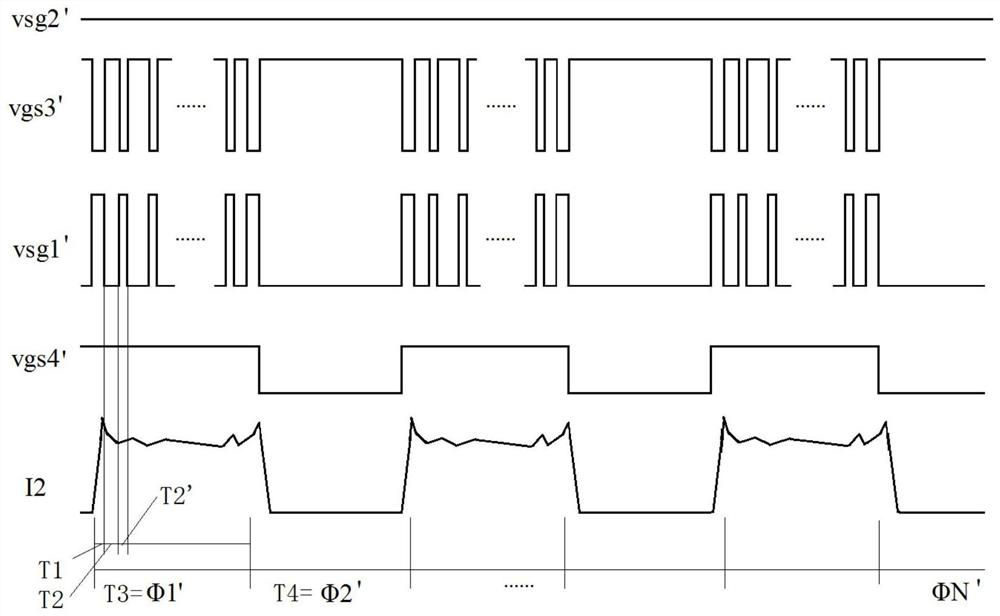
[0030] A method for starting or anti-locking a DC brushed motor, which is different from the prior art in that, in addition to including a traditional overcurrent protection circuit, an overtemperature protection circuit and such as figure 1 The H-bridge driving circuit shown also includes a PWM control module, and the PWM control module P1 controls the first high-side PMOS switch M1, the second high-side PMOS switch M2, the third The low-side NMOS switch M3 and the fourth low-side NMOS switch M4 are turned on and off. The PWM control module P1 is preset with a modulation current threshold Ipwm and a modulation current startup time tp, the modulation current threshold Ipwm is at most not greater than the overcurrent protection threshold Iocp, and the minimum is not less t...


PUM


Abstract

The invention provides a starting or anti-locked-rotor method of a direct-current brush motor. According to the method, a working current is modulated through a PWM control module on the basis of a traditional over-current protection period, so that a load current exists in a process of the first half period of slow attenuation of each current, and the load current is stabilized at a modulation current threshold value, namely, safe and constant starting torque can still be provided for a direct-current brush motor; in a second half cycle process of each current fast attenuation, PWM modulation is not carried out, and the direct-current brush motor loses the driving torque and freely slides, namely, cyclic actions of starting, sliding, starting, sliding, starting and like of the direct-current brush motor are achieved, wherein the two modes are switched at intervals, so that the winding coil of the direct current brush motor shakes, and then rotation inertia is generated, so that the static moment of the direct current brush motor is weakened by the rotation inertia, and the constant starting torque of the direct-current brush motor is added so as to finally achieve the safe starting of the direct-current brush motor.

Description

technical field [0001] The invention relates to the driving technology of a DC brushed motor, in particular to a method for starting or anti-locking a DC brushed motor. Background technique [0002] Such as figure 1 Shown is a schematic diagram of the principle of the H-bridge drive circuit of the H-bridge driver driving the DC brushed motor. The DC brushed motor is simplified as an inductive load LR. In the H-bridge drive circuit, the first high-side PMOS switch tube M1 and the third low-side The drain of the side NMOS switch M3 is connected to the first node A, the second high-side PMOS switch M2 and the fourth low-side NMOS switch M4 are connected to the second node B, and one end of the inductive load is connected to the first node A , the other end is connected to the second node B, where D1, D2, D3, and D4 are respectively the first high-side PMOS switch M1, the second high-side PMOS switch M2, the third low-side NMOS switch M3, and the fourth low-side The parasitic ...

Claims


Application Information

Patent Timeline
Patent Type & Authority Applications(China)
IPC IPC(8): H02P1/18H02P29/10H02P29/40H02P29/024
CPCH02P1/18H02P29/10H02P29/40H02P29/027
Inventor 张长洪
Owner SG MICRO
Why Eureka
Try Eureka