Box-type switching station

A switch station and box-type technology, applied in substation/switch layout details, substation/switchgear cooling/ventilation, electrical components, etc., can solve the problems of limited operating space for staff, difficult deployment, and reduced service life of components. , to achieve the effect of increasing display space, increasing heat dissipation efficiency, and improving work efficiency

Inactive Publication Date: 2021-07-16
江苏江阴华明电气设备有限公司
View PDF0 Cites 0 Cited by
  • Summary
  • Abstract
  • Description
  • Claims
  • Application Information

AI Technical Summary

Problems solved by technology

[0003] The current box-type switchgear is generally installed and installed outside. However, the outside climate is changeable. In hot weather, the heat source generated by the current flow in the device will be larger, which will cause the heat dissipation system to be unable to fully discharge the heat source in the equipment and increase the number of components. In the rainy season, external moisture can easily enter the device, making the components damp, affecting the normal use of the equipment, reducing the safety measures for the actual use of the equipment, reducing the functionality of the device and the practical value of the external assembly; in the equipment It is often necessary to open the switchgear during assembly or follow-up maintenance of the components. However, the space of the box-type switchgear is limited and it is not easy to fully expand, which limits the operating space of the staff and increases the work of maintenance and parts installation. The implementation is difficult and inconvenient. When the heat dissipation system in the equipment is in operation, the gas conductivity is poor, and the heat source is easy to concentrate in the equipment in large quantities, which cannot be quickly drained, thereby increasing the heating surface and damage of the components in the equipment and reducing the components. service life

Method used


Image

  • Box-type switching station
  • Box-type switching station
  • Box-type switching station

Examples


Embodiment 1

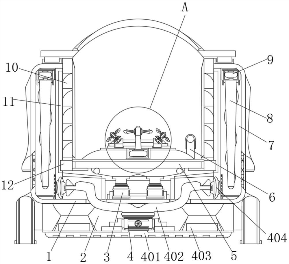
[0038] Example 1, such as figure 1 As shown, the humidity under the equipment is detected by the humidity sensor 403. When the humidity reaches a certain index, the suction fan 4 and the servo motor 9 can be started through the control box 13, and the cooling gas inside the inner box 5 is released from the exhaust port 10. After the outflow, the start of the servo motor 9 can drive the spiral guide rod 8 to guide the gas downward, and after the gas is introduced into the lower part, the start of the suction fan 4 and the communication and cooperation of the shunt pipe 402 and the suction port 404 will guide the flow. The gas under the wind chamber 7 is absorbed, and the absorbed gas flows into the permeable plate 401 under negative pressure, and through the evenly distributed through holes of the permeable plate 401, the absorbed heat dissipation gas evenly covers the bottom groove 2 and the bottom of the permeable plate 401, Furthermore, the moisture sensed by the humidity se...

Embodiment 2

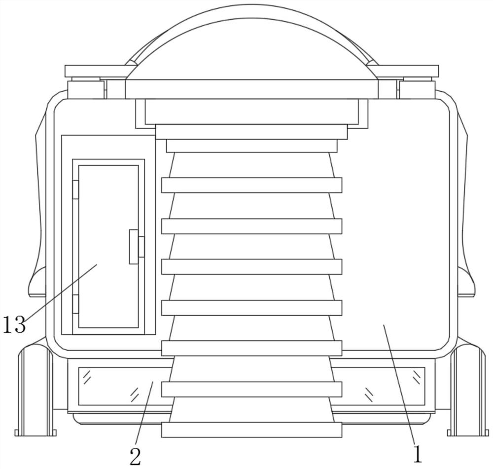
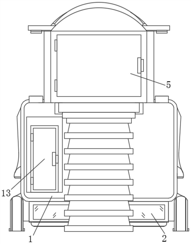
[0039] Example 2, such as Figure 1-3 As shown, the temperature in the inner box 5 is detected by the temperature sensor 6. When the temperature in the inner box 5 is high, the electric push rod 3 can be started through the control box 13, and the start of the electric push rod 3 is used to drive the inner box. The box body 5 is lifted as a whole, and during the rising of the inner box body 5, four groups of guide blocks 12 are driven to slide and rise under the cooperation of the guide rail columns 11, so that the inner box body 5 can be fully expanded out of the outer box body 1. At this time, the first The fan blades 145 and two sets of second fan blades 146 perform heat dissipation, and the radiated gas can be directly discharged from the exhaust port 10 to speed up the circulation of the gas, prevent the heat source from being concentrated in the equipment and affect the components, and use steps and platforms to After the inner box body 5 is unfolded, the structural comp...


PUM


Abstract

The invention discloses a box-type switching station which comprises an outer box body, a bottom groove is formed in the bottom of the outer box body, air guide cavities are formed in the two sides of the interior of the outer box body, guide rail columns are arranged at the two ends of the two sides of the interior of the outer box body, and guide blocks matched with one another are arranged on the inner sides of the four guide rail columns, inner box bodies connected with each other are arranged on the sides, close to each other, of the two guide blocks on the same side. Through mutual cooperation of heat dissipation and air exhaust assemblies, heat dissipation air can be formed in the inner box bodies through rotation of first fan blades and two sets of second fan blades which are obliquely arranged, and the second fan blades are forced to rotate in a surrounding mode under meshing of a rotating rod and a bevel gear ring through rotary sliding of a sliding block and an annular sliding groove, and meanwhile, the heat dissipation air exhausted from the inner box bodies can form flow guide in the air guide cavities under the cooperation of two sets of servo motors and spiral flow guide rods, the heat dissipation air can be rapidly exhausted from the outer box body, and the heat dissipation efficiency of the device is improved.

Description

technical field [0001] The invention relates to the technical field of power distribution equipment, in particular to a box-type switchgear. Background technique [0002] The switch station refers to the power supply and distribution facilities used to receive and distribute power. The high-voltage power grid is called a switch station. The switch station in the medium-voltage power grid is generally used for receiving and distributing 10kV power. There is a medium-voltage power distribution facility. The power distribution device for incoming and outgoing lines and redistribution of power is equivalent to the extension of the substation busbar. It can be used to solve the limited interval between the incoming and outgoing lines of the substation or the restricted corridor of the incoming and outgoing lines, and play the role of power supply in the area. [0003] The current box-type switchgear is generally installed and installed outside. However, the outside climate is cha...

Claims


Application Information

Patent Timeline
Patent Type & Authority Applications(China)
IPC IPC(8): H02B7/06H02B1/46H02B1/56H02B1/28
CPCH02B1/28H02B1/46H02B1/565H02B7/06
Inventor 龚剑沈刘叶杨醒武吴晓蕾刘志叶王文炎
Owner 江苏江阴华明电气设备有限公司
Why Eureka
Try Eureka