Micro light emitting diode display system

A micro-light-emitting diode and display system technology, applied in static indicators, instruments, semiconductor devices, etc., can solve the problems of difficult to reduce the number of row/column drivers, low pixel resolution, difficult to reduce the number, etc., and achieve low speed and energy consumption , high pixel resolution, reduced number of effects

Active Publication Date: 2021-07-16
RAYDIUM SEMICON
View PDF5 Cites 0 Cited by
  • Summary
  • Abstract
  • Description
  • Claims
  • Application Information

AI Technical Summary

Problems solved by technology

[0012] However, the traditional micro light-emitting diode integrated circuit μIC still has many shortcomings / problems in practical applications, such as: (1) high power consumption (Power consumption); (2) low frame rate (Frame rate); (3) low pixel Resolution (Pixelresolution); (4) It is difficult to reduce the number of pins (Pin); and (5) It is difficult to reduce the number of row / column drivers (Row / column driver), which needs to be further overcome

Method used


Image

  • Micro light emitting diode display system
  • Micro light emitting diode display system
  • Micro light emitting diode display system

Examples


Embodiment Construction

[0111] Reference will now be made in detail to the exemplary embodiments of the present invention, examples of which are illustrated in the accompanying drawings. Elements / components with the same or similar numbers used in the drawings and the embodiments are used to represent the same or similar parts.

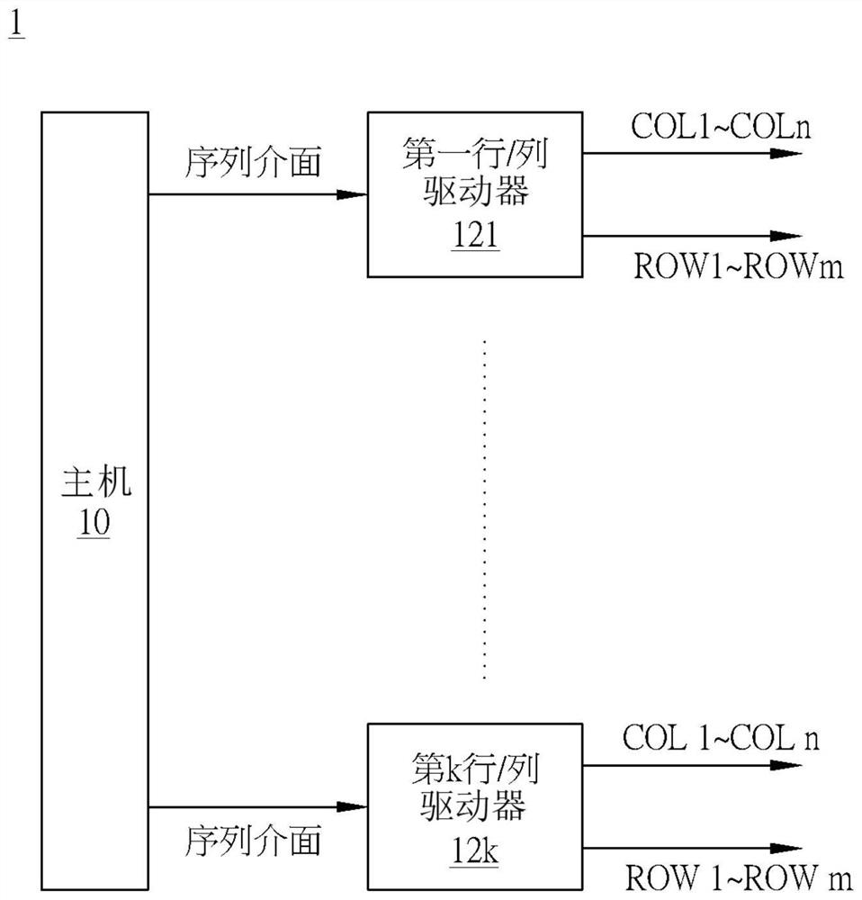
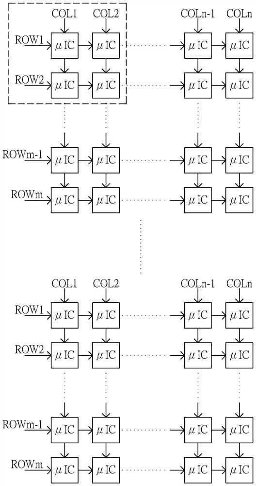
[0112] A specific embodiment according to the present invention is a micro-light-emitting diode (MICRO-LED) display system, such as an active matrix (Active Matrix) micro-light-emitting diode display system, which includes multiple row / column drivers and multiple micro-light-emitting diodes Integrated Circuit (μIC), but not limited thereto. As for its overall structure, please refer to Figure 1 and figure 2 , which will not be described further here.

[0113] Next, the micro LED integrated circuit (μIC) in several different embodiments proposed by the present invention will be described in detail respectively.

[0114] In the first embodiment, if Figure 5 As shown, the...


PUM


Abstract

The invention discloses a micro light emitting diode display system. The micro light emitting diode display system comprises a host, a plurality of row / column drivers and a plurality of micro light emitting diode integrated circuits. The plurality of row / column drivers are respectively coupled to the host through a sequence interface and are used for respectively providing a plurality of row clock signals and a plurality of column data signals. The plurality of micro light emitting diode integrated circuits are arranged in a matrix, and the matrix comprises a plurality of columns of micro light emitting diode integrated circuits and a plurality of rows of micro light emitting diode integrated circuits which are respectively used for receiving the plurality of column data signals and the plurality of row clock pulse signals. All the micro light-emitting diode integrated circuits in the same column of micro light-emitting diode integrated circuits are sequentially connected in series, and all the micro light-emitting diode integrated circuits in the same row of micro light-emitting diode integrated circuits are sequentially connected in series.

Description

technical field [0001] The invention relates to a display device, in particular to a micro light emitting diode display system. Background technique [0002] Such as Figure 1A and Figure 1B As shown, a traditional micro-light-emitting diode display system 1 includes a host 10, a first row / column driver 121 to a k-th row / column driver 12k, and (k*m*n) micro-light-emitting diode integrated circuits μIC, where k, m , n are both positive integers. [0003] The host 10 is respectively coupled to the first row / column driver 121 to the kth row / column driver 12k through a serial interface. The (k*m*n) micro light emitting diode integrated circuits μIC are arranged in the form of k (m*n) matrix. The first row / column driver 121 to the kth row / column driver 12k are used to respectively couple and drive the k (m*n) micro light-emitting diode integrated circuits μIC arranged in a matrix. [0004] Taking the first row / column driver 121 as an example, the first row / column driver 121 ...

Claims


Application Information

Patent Timeline
Patent Type & Authority Applications(China)
IPC IPC(8): G09G3/32
CPCG09G3/32H01L25/167G09G3/2088G09G2310/0267G09G2310/0286G09G2310/08G09G2310/027G09G2300/0857H01L27/156
Inventor 李冠贤詹前煜梁彦雄罗友龙
Owner RAYDIUM SEMICON
Why Eureka
Try Eureka