
Intelligent sensing method for heat source overload of skin array unit

An array unit, intelligent perception technology, applied in the field of electronics, can solve the problems of multi-system resources, sensor failure, reduce the reliability of temperature signal transmission, etc., to achieve the effect of strong robustness and high intelligence

Active Publication Date: 2021-07-16
SOUTHWEST CHINA RES INST OF ELECTRONICS EQUIP
View PDF5 Cites 0 Cited by
  • Summary
  • Abstract
  • Description
  • Claims
  • Application Information

AI Technical Summary

Problems solved by technology

At present, the main monitoring method is mainly to report the temperature of the chip junction. The monitoring method used in the industry is also relatively mature on the ground equipment. , temperature shock, etc. Short circuit or open circuit makes the sensor invalid, so that the reliability of temperature signal transmission is reduced, and the use of wireless sensors is faced with the problem of occupying more system resources. In actual engineering, it is urgent to overload the heat source of the array system unit Real-time monitoring of the actual situation of the environment requires a low-cost, flexible and easy-to-configure new technical means to play a role in the temperature monitoring of aerospace high-heat-consuming electronic systems
[0004] To sum up, the current monitoring method of skin array unit heat source overload temperature can not take into account the detection accuracy and the proportion of system resources without greatly increasing the complexity of the system. It has certain limitations and is not enough to meet the current The temperature overload monitoring requirements of high heat source electronic systems and provide real-time and accurate regulation for the corresponding sub-array switch topology scheme

Method used


Image

  • Intelligent sensing method for heat source overload of skin array unit
  • Intelligent sensing method for heat source overload of skin array unit
  • Intelligent sensing method for heat source overload of skin array unit

Examples


Embodiment Construction

[0040] In order to make the object of the present invention, the technical scheme will be clearly described in connection with the embodiment of the present invention, and is clearly described, and the embodiments described are intended to be described in connection with the embodiments of the present invention. Method, not all of the implementation. Based on the embodiments in the present invention, those of ordinary skill in the art are in the range of the present invention without making creative labor premistence. Thus, the detailed description of the embodiments of the invention as claimed below is not intended to limit the scope of the invention claims, but only the selected embodiments of the present invention.

[0041] In the description of the present invention, it is to be understood that the terms indicating a orientation or positional relationship are based on the orientation or positional relationship shown in the drawings, but is intended to facilitate the descriptio...


PUM


Abstract

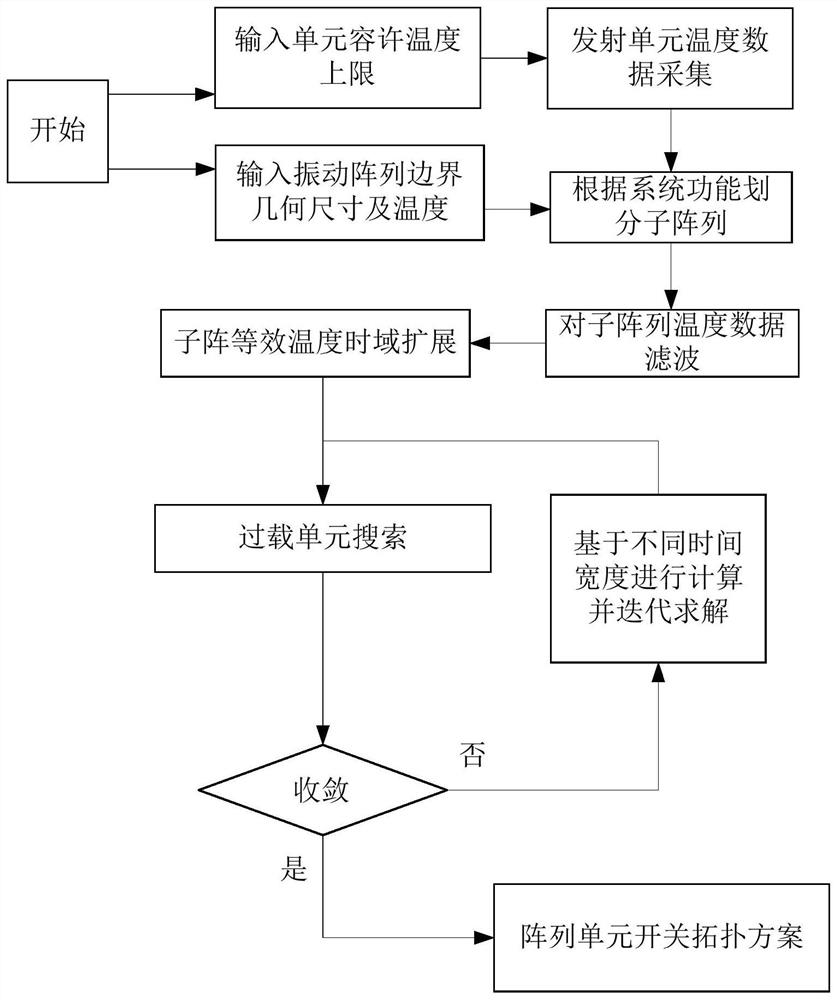
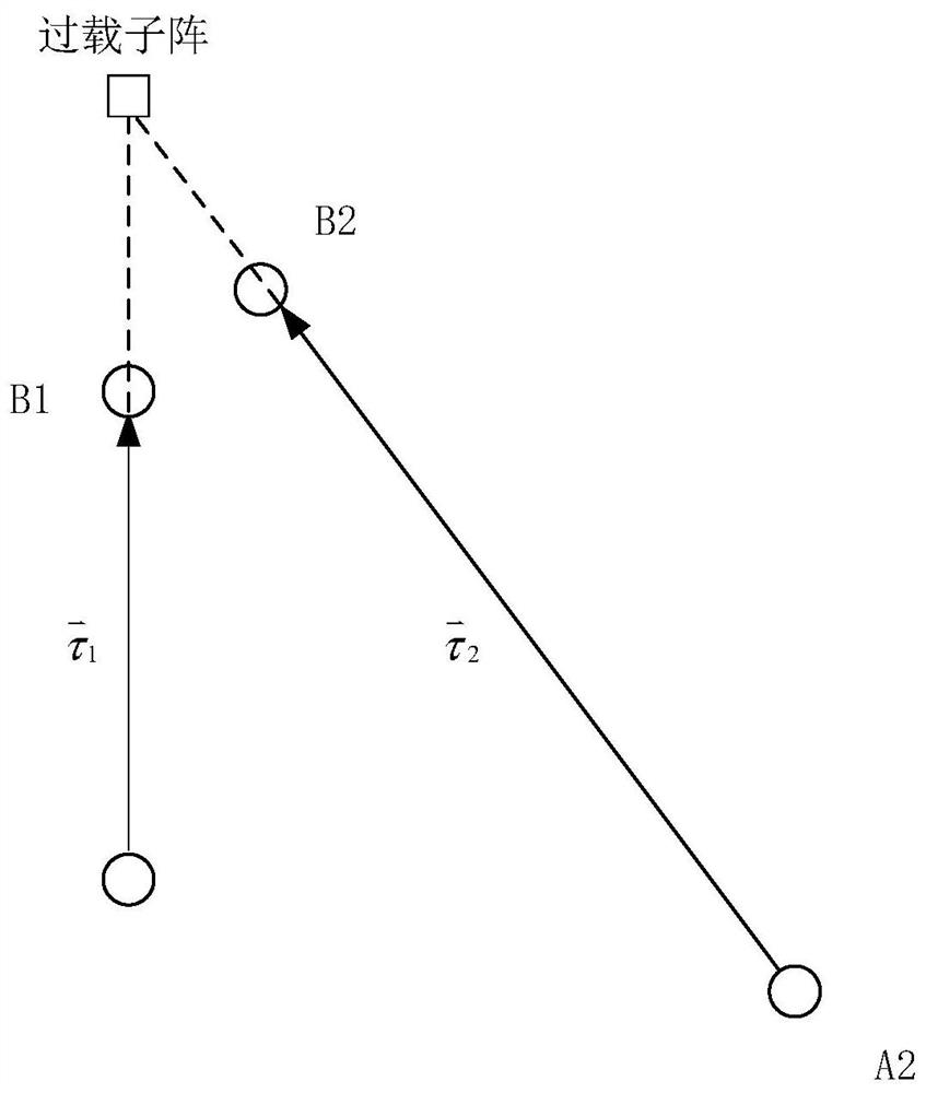
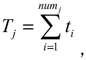
The invention specifically discloses an intelligent sensing method for heat source overload of a skin array unit. The method comprises the following steps: inputting a temperature design boundary required by a system for the array unit, an allowable temperature upper limit of the unit, a geometric dimension of a vibration array boundary and a temperature; dividing the array unit into sub-arrays, performing temperature data acquisition on the transmitting unit, and calculating a sub-array equivalent temperature value; performing time domain data expansion on the equivalent temperature values of the sub-arrays to obtain a jth sub-array temperature vector, and storing the equivalent values of the plurality of sub-arrays; determining a plurality of overload heat source direction vectors, determining the geometric space position of an overload source through a cross positioning mode, and obtaining a determined subarray through convergence; and providing an array cell switch topology scheme to a system control center to prevent overload damage. According to the method, the detection accuracy and the system resource proportion can be considered, and certain accuracy of real-time temperature monitoring is ensured on the premise that the system resource proportion is not increased.

Description

Technical field [0001] The present invention relates to the field of electronic technology, and is applied to the design of the skin, sub-array equivalent temperature time domain expansion, overload unit search, and array unit switch topology scheme, more specifically, involved in an aviation environment. Intelligent perception method of the skin of the skin array unit. Background technique [0002] Recently, the rapid development of aerospace electronic equipment, the application of high integration array system is very wide, and the heat source of high heat flow density is increasing. However, in the actual engineering, the chip generates a thermal overload due to the unreasonable planning of the radiating topology, and the power mismatch, and the chip will generate a thermal overload. After a certain overload time, it will be damaged by the sub-array unit, and the chip is reported to report data. There is a certain deviation or even errors, and the sub-array of high integratio...

Claims


Application Information

Patent Timeline
Patent Type & Authority Applications(China)
IPC IPC(8): G06F30/20G06F16/22G06F119/08
CPCG06F30/20G06F16/22G06F2119/08
Inventor 冷国俊肖滨李佳保宏王从思黄永安蒙春城赖天华廖长江王伟陈显才张逸群
Owner SOUTHWEST CHINA RES INST OF ELECTRONICS EQUIP
Learn More