
High-brightness multi-channel optical machine structure

A high-brightness, multi-channel technology, applied in optics, instruments, projection devices, etc., can solve the problems of VOC carbonization and blackening, reducing brightness, etc.

Active Publication Date: 2021-07-16
DIGIENGIN OPTOELECTRONICS TAIZHOU LTD CO
View PDF3 Cites 0 Cited by
  • Summary
  • Abstract
  • Description
  • Claims
  • Application Information

AI Technical Summary

Problems solved by technology

[0004] The purpose of the present invention is to provide a high-brightness multi-channel optical engine architecture to solve the problem that the existing multi-channel projection optical engine equipment easily excites the VOC of the thermal interface material The problem of reducing brightness due to carbonization and blackening

Method used


Image

  • High-brightness multi-channel optical machine structure
  • High-brightness multi-channel optical machine structure
  • High-brightness multi-channel optical machine structure

Examples


Embodiment 1

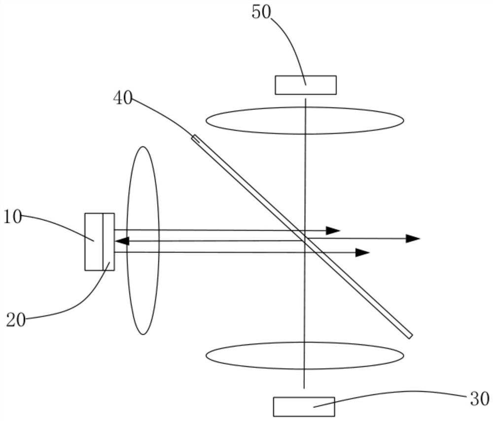
[0054] See figure 1 , A multi-channel optical machine architecture provided by the first embodiment of the present invention, including:

[0055] The first solid state light-emitting chip 10, the first solid state light-emitting chip 10 is used to emit light of the first spectrum, wherein the light of the first spectrum can be green or red.

[0056] The first fluorescent sheet 20 is provided at the light emitting end of the first solid state light emitting chip 10, wherein the first fluorescent sheet 20 is close to the first solid light emitting chip 10 through a high thermal conductive interface material. ;

[0057] The first excitation optical chip 30 is used to emit first excitation light, wherein the first excitation light is excited blue.

[0058] The first combined light filter 40 is used to guide the first excitation light incident the first fluorescent sheet from the top side of the first fluorescent sheet 20, and generates An excited light, in particular, the first-fittin...

Embodiment 2

[0065] In one embodiment of the invention, please refer to figure 1 Most of the first spectrum of the first spectrum is transmitted through the first fluorescent sheet 20 without excitation, and at least 80% spectrum overlap with the first excited light. . Example three

Embodiment 3

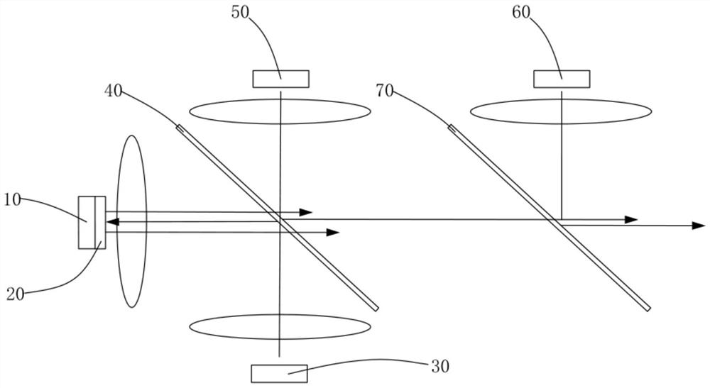
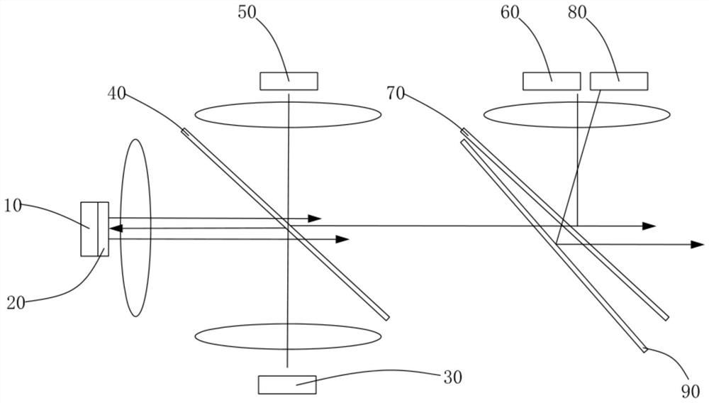
[0066] In one embodiment of the invention, please refer to figure 2 The multi-channel optical architecture of the high brightness also includes a third solid state light-emitting chip 60 and a second engaging light filter 70; the third solid light-emitting chip 60 is used to transmit the third spectrum, the third spectrum of light can For green light, it is protected green or blue; if the light of the second spectrum is blue, the light of the third spectrum is green or excited green. If the light of the second spectrum is green, then the third spectrum Light is blue; wherein the first spectrum of light, the first excited light, the second spectrum of light, and the third spectrum of light are photographed by the first plexamethum filter 40 and the The second engaged light filter 70 is combined into the coaxial light, without increasing the optical expand, constitutes a multi-channel architecture of high brightness, wider color gamut, and small light energy, no evaporation of hairl...


PUM

PropertyMeasurementUnit
wavelengthaaaaaaaaaa

Abstract

The invention provides a high-brightness multi-channel optical machine structure. The structure comprises a first solid-state light-emitting chip, a first fluorescent sheet, a first excitation light chip, a first light combination filter, and a second solid-state light-emitting chip; the first solid-state light-emitting chip is used for emitting light of a first spectrum; the first fluorescent sheet is arranged at the light-emitting end of the first solid-state light-emitting chip; the first excitation light chip is used for emitting a first excitation light spectrum; the first light combination filter is used for guiding the first excitation light spectrum to enter the first fluorescent sheet from the top side of the first fluorescent sheet and generating first excited light, and the first excited light is reflected by the bottom of the first solid-state light-emitting chip and then is combined with the light of the first spectrum, light is separated from the first light combination filter, so that synthesized emergent light can be obtained; and the second solid-state light-emitting chip is used for emitting a second spectrum. According to the high-brightness multi-channel optical machine structure, the high-brightness multi-channel optical machine structure is wider in color gamut and small in light energy and avoids the evaporation of volatile organic compounds; and the problem of VOC carbonization is solved.

Description

Technical field [0001] The present invention relates to the technical findings of a multi-channel projection optical engine device, and more particularly to a multi-channel optical machine architecture. Background technique [0002] Multi-channel projection optical engine equipment, prior art uses R / g / B light and mix together to obtain white and bright color images. The conventional projection light engine is made of red, green, and Lan three-channel, where green light can be a semiconductor luminescent green light excitation light, a narrow spectrum bandwidth, high image color saturation or NTSC color domain; green light can also be fluorescent Excunum light, high green flux, but spectral bandwidth, color saturation is slightly less than. Since the luminance of the three lamps has some limitations, several techniques have been proposed in the industry to increase the number of light sources that can be used to increase the brightness of the projection system. [0003] In ord...

Claims


Application Information

Patent Timeline
Patent Type & Authority Applications(China)
IPC IPC(8): G03B21/20
CPCG03B21/204
Inventor 翟金会
Owner DIGIENGIN OPTOELECTRONICS TAIZHOU LTD CO
Learn More