
a projector

A technology of projectors and prisms, which is applied in the field of projectors, can solve the problems of affecting the service life, increasing the volume of projectors, and complex structures, and achieves the effects of improving brightness, simple structure, and small volume

Inactive Publication Date: 2019-08-02
IVIEW DISPLAY SHENZHEN CO LTD
View PDF9 Cites 0 Cited by
  • Summary
  • Abstract
  • Description
  • Claims
  • Application Information

AI Technical Summary

Problems solved by technology

[0003] At present, projectors generally use one light source as the projection light source. Although the structure is simplified, it also occurs that only one light source is used in a high-brightness environment, and the brightness cannot meet user needs, such as outdoor
The existing method of increasing brightness is to use fluorescent powder or fluorescent color wheel, which not only makes the structure more complicated, but also increases the volume of the projector, and also causes a large heat dissipation burden on the projector, which affects the service life

Method used


Image

  • a projector
  • a projector
  • a projector

Examples


Embodiment 1

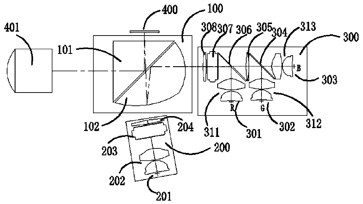
[0023] like figure 1 Shown is a schematic structural diagram of the projector of the present invention, including: a first light source group 300 that generates RGB primary colors and a light supply module of a second light source group 200 that generates a red laser light source, that is, an enhanced light source 201, a first prism unit, and a second lens The first light combination module 100 , the image display module 400 for generating projected images, and the lens 401 for receiving reflected images from the first light combination module 100 are composed of units.

[0024] The image display module 400 is placed opposite to the second light source group 200 and respectively located on both sides of the first light combination module 100 , the lens 401 is placed opposite to the first light source group 300 and respectively located on the other two sides of the first light combination module 100 , The RGB three primary colors light generated by the first light source group ...

Embodiment 2

[0048] like Figure 4 The main difference between the structure of the projector shown in Embodiment 1 is that the first light source group 310 and the second light source group 206 of the light supply module are different from Embodiment 1, and the rest of the structure is the same as Embodiment 1.

[0049] Among them, the main difference between the first light source group 310 and the first light source group 300 in Embodiment 1 is that the first light source group 310 in this embodiment uses two color lights in the three primary colors as the first light source, and the color light selected in this embodiment It is blue light and green light, so compared with the first light source group 300 in the first embodiment using three primary colors of light as the light source, this embodiment omits the first relay lens 305 and the second beam splitter 306, other structures and The arrangement remains unchanged.

[0050] Wherein, the main difference between the second light sour...


PUM


Abstract

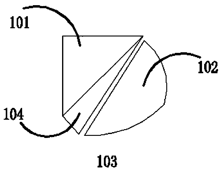
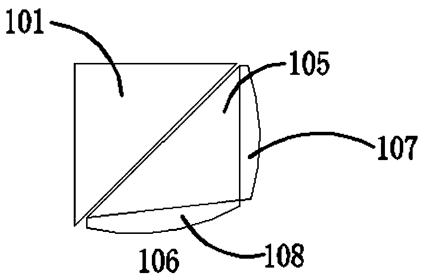
Disclosed is a projector, comprising: a light combining module (100) comprising a first prism unit and a second lens unit; a light supplying module comprising a first light source group (300) and a second light source group (200); and an image display module (400) and a lens (401). There is a gap between the first prism unit and the second lens unit of the light combining module (100), and the surfaces thereof which are close to each other are all planes. The image display module (400) and the second light source group (200) are arranged opposite each other and respectively located on two sides of the light combining module (100). The lens (401) and the first light source group (300) are arranged opposite each other and are located on the other two sides of the light combining module (100) respectively. The light combining module (100) is used for transmitting and reflecting the light from the first light source group (300) and the second light source group (200), such that the light from the first light source group (300) and the second light source group (200) is combined and then projected to the image display module (400) for modulation and display. The image displayed by the image display module (400) is reflected by the light combining module (100) and then emitted to the lens (401). By means of the integration of light paths by the light combining module (100), the projector has a simple structure and small size.

Description

technical field [0001] The invention relates to the technical field of projection display, in particular to a projector. Background technique [0002] Most of the current miniature projection light machines adopt the DLP technology of Texas Instruments, and its main image and light control devices are generally called DMD light modulators. It is a micro-mirror array with extremely high reflectivity. It needs to cooperate with the illumination optical system and the projection optical system to convert the commonly used RGB three primary colors into a projection image that is easy to see for our eyes. One of the commonly used methods of combining the illumination optical system and the projection optical system is to use a total internal reflection element having a lens surface. [0003] At present, projectors generally use one light source as the projection light source. Although the structure is simplified, it also happens that only one light source is used in high-brightn...

Claims


Application Information

Patent Timeline
Patent Type & Authority Patents(China)
IPC IPC(8): G03B21/20G02B27/10
CPCG02B27/10G03B21/20
Inventor 高志强杨伟樑赵远宁曼莹
Owner IVIEW DISPLAY SHENZHEN CO LTD
Learn More