An anti-blocking infrared thermometer
An infrared thermometer and infrared temperature technology, applied in the direction of instruments, measuring devices, scientific instruments, etc., can solve the problems of uncertain coking time, no anti-blocking function, blockage, etc., and achieve high degree of automation, high safety and reliability measured effect
- Summary
- Abstract
- Description
- Claims
- Application Information
AI Technical Summary
Problems solved by technology
Method used
Image
Examples
Embodiment 1
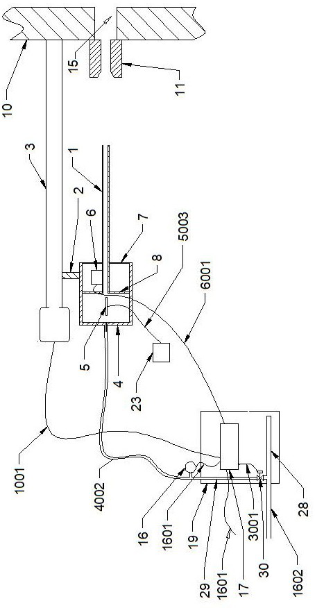
[0036] Embodiment one: if figure 1 As shown, an anti-blocking infrared thermometer of the present invention includes a light guide 1, a propeller 3, a vibrator 6, a connecting block 2, an infrared lens group 5, an infrared temperature sensor 23, a housing 4, a fixing plate, Pressure transmitter 16, control device and fire detection hole sealing assembly;
[0037] The propeller 3 adopts electric propulsion, the propeller 3 and the light guide tube 1 are arranged horizontally along the left and right sides, the right end of the propeller 3 is fixed on the left outer wall of the kiln 10, the propeller 3 is connected with the shell 4 through the connecting block 2, and the infrared lens The group 5 and the vibrator 6 are set in the housing 4, the left end of the light guide tube 1 extends into the housing 4 and is fixedly connected with the housing 4 through the fixing piece (including the first fixing piece 7 and the second fixing piece 8), and the vibrator 6 Arranged on the lig...
Embodiment 2
[0045] Embodiment two: if figure 2 As shown, the difference between this embodiment and Embodiment 1 is that
[0046] Also be provided with the second control circuit board 18 in the control box 19, the second control circuit board 18 is connected with the first control circuit board 17 by the fifth wire 1801, the signal output end of the infrared temperature sensor 23 and the second control circuit board 18 The signal input terminal is connected, and the furnace temperature signal of the kiln 10 detected by the infrared temperature sensor 23 is sent to the second control circuit board 18 through the sixth wire 2301, and the second control circuit board 18 outputs a vibration request signal to the first control circuit board 17 ;
[0047] The control logic of the second control circuit board 18 is as follows: when the furnace temperature signal reduction value ≥ x, and the vibration interval time is greater than y1 seconds, a vibration request signal is sent; when the vibrat...
Embodiment 3
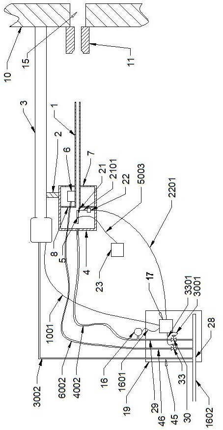
[0055] Embodiment three: as image 3 As shown, compared with Embodiment 1, the propeller 3 of this embodiment adopts a pneumatic propeller 3 , the vibrator 6 adopts a pneumatic vibrator, and a camera 21 is arranged at the rear of the light guide 1 .
[0056] The propeller 3 is connected to the gas source main pipe 28 through the third air guide pipe 3002 and the third gas source branch pipe 45, and the propulsion and withdrawal power of the propeller 3 comes from compressed gas.
[0057] The vibrator 6 is connected to the fourth air source control valve 33 through the fourth air guide pipe 6002 and the fourth air source branch pipe 46. The fourth air source control valve 33 adopts a solenoid valve type, and the fourth air source control valve 33 is connected to the air source On the main pipe 28, the control signal of the fourth air source control valve 33 is connected to the first control circuit board 17 through the tenth wire 3301, and the first control circuit board 17 dri...
PUM
 Abstract
Description
Claims
Application Information
 - R&D
- Intellectual Property
- Life Sciences
- Materials
- Tech Scout
- Unparalleled Data Quality
- Higher Quality Content
- 60% Fewer Hallucinations
Browse by: Latest US Patents, China's latest patents, Technical Efficacy Thesaurus, Application Domain, Technology Topic, Popular Technical Reports.
© 2025 PatSnap. All rights reserved.Legal|Privacy policy|Modern Slavery Act Transparency Statement|Sitemap|About US| Contact US: help@patsnap.com


