A split-flow cooled aeroengine compressor rear shaft diameter tapered wall cavity

A technology of aero-engines and compressors, which is applied in the direction of machines/engines, liquid fuel engines, and parts of pumping devices for elastic fluids, etc. It can solve the problem of failure to achieve reasonable distribution and utilization of airflow, failure to achieve cooling effects, etc. problems, to achieve the effect of reducing wind resistance, improving cooling quality, and precise cooling

Active Publication Date: 2022-01-28
BEIHANG UNIV
View PDF7 Cites 0 Cited by
  • Summary
  • Abstract
  • Description
  • Claims
  • Application Information

AI Technical Summary

Problems solved by technology

Therefore, the lower half of the cone wall and the components downstream of the cone wall cavity often cannot achieve a good cooling effect
[0004] Although the above-mentioned single-position bleed air cooling scheme adopted by the traditional aero-engine cone wall cavity can meet the cooling requirements of early engines, in advanced aero-engines, the temperature level is further increased, and the traditional method cannot achieve reasonable airflow. allocation and utilization, so no longer applies

Method used


Image

  • A split-flow cooled aeroengine compressor rear shaft diameter tapered wall cavity
  • A split-flow cooled aeroengine compressor rear shaft diameter tapered wall cavity
  • A split-flow cooled aeroengine compressor rear shaft diameter tapered wall cavity

Examples


Embodiment Construction

[0025] The technical solutions in the embodiments of the present invention will be clearly and completely described below in conjunction with the accompanying drawings in the embodiments of the present invention. Obviously, the described embodiments are only for illustration and are not intended to limit the present invention.

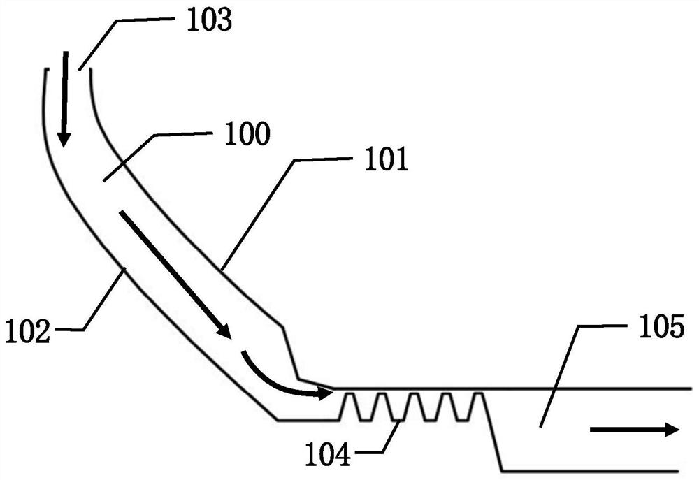
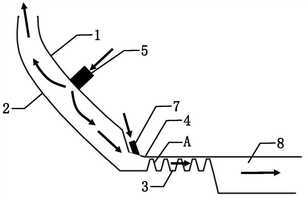
[0026] The invention provides a split-cooled aero-engine compressor rear shaft diameter tapered wall cavity, such as figure 2 As shown, it is formed by the stator cone surface 1, the rotor cone surface 2 opposite to the stator cone surface 1, the grate element 3 and the stator drum surface 4 opposite to the grate element 3;

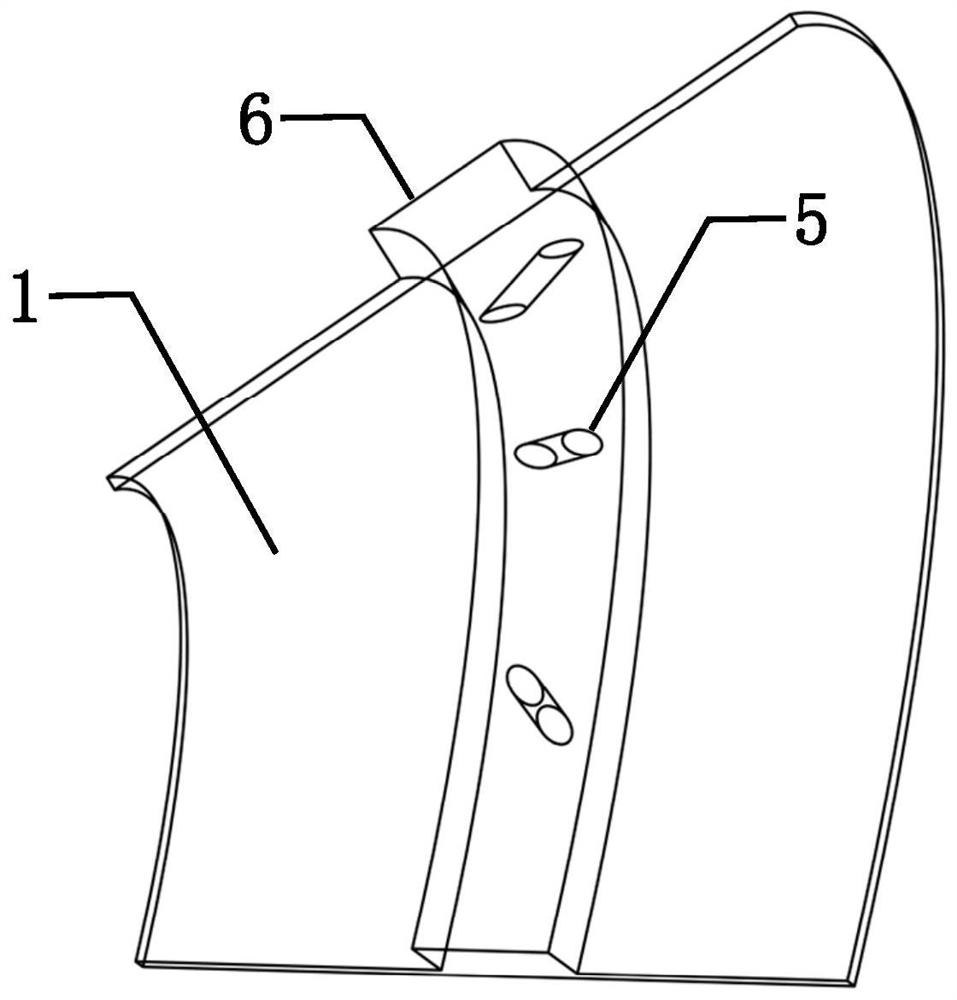
[0027] In the middle position along the height direction of the stator cone surface 1, within the range of upward and downward deviations of 10mm respectively, a circle of first bosses are provided along the circumference of the stator cone surface 1, and a plurality of first pre-rotation platforms are arranged on the first bosses...


PUM


Abstract

The invention discloses a split-cooled aeroengine compressor rear shaft diameter cone wall cavity, which is different from the traditional aeroengine air system components in which a single type of air-introduction hole is provided for air-intake cooling, but the stator cone surface and the stator drum respectively The pre-rotating nozzles with two apertures on the surface can not only realize the reasonable distribution of the cooling air flow and the reasonable configuration of the cooling parts under the condition of the total flow of the bleed air, so as to achieve precise cooling, but also shorten the flow of the cooling air in the flow channel. The flow distance can significantly reduce the wind resistance of the rotor to the cooling airflow, reduce the entropy of the airflow, improve the quality of the cold air, and can also ensure the cooling quality of the airflow out of the cone wall cavity while ensuring that the cone wall is in a comprehensive and good cooling state. The improvement of the cone wall cavity makes the downstream components get better cooling effect. The invention conforms to the low-entropy production design concept of the flow path of the air system, and can be widely used in the cooling scheme design of the air system of the advanced aeroengine.

Description

technical field [0001] The invention relates to the field of aero-engines, in particular to a split-flow cooled aero-engine compressor rear shaft diameter tapered wall cavity. Background technique [0002] With the continuous improvement of aero-engine performance, the temperature before the turbine is getting higher and higher, which puts forward higher requirements for material technology and aero-engine air system cooling technology. At present, the application of aero-engine material technology has reached the extreme state. High-temperature material technology alone cannot meet all design requirements, and the remaining cooling requirements must be realized by the aero-engine air system. Normally, increasing the bleed air flow of the air system will directly improve the cooling effect of the air system, but the increase of the air system flow will lead to the decline of the overall performance of the engine. Therefore, how to reasonably distribute the cooling airflow a...

Claims


Application Information

Patent Timeline
Patent Type & Authority Patents(China)
IPC IPC(8): F04D29/58F04D29/52
CPCF04D29/582F04D29/522
Inventor 邱天丁水汀邓长春赵煜王承昊袁奇雨刘传凯刘晓静
Owner BEIHANG UNIV
Why Eureka
Try Eureka