
A turbine outer ring block air supply structure with separate chamber air supply

A cavity-dividing and turbine technology, applied in the directions of blade support elements, machines/engines, and mechanical equipment, can solve the problem of reduced intake and exhaust pressure, large axial pressure gradient at the outlet of the outer ring block, and excessive cooling of the outer ring block. Loss and other problems, to achieve the effect of enhancing the cooling effect and reducing the increase in the air bleed volume of the air system

Active Publication Date: 2022-05-10
BEIHANG UNIV
View PDF5 Cites 0 Cited by
  • Summary
  • Abstract
  • Description
  • Claims
  • Application Information

AI Technical Summary

Problems solved by technology

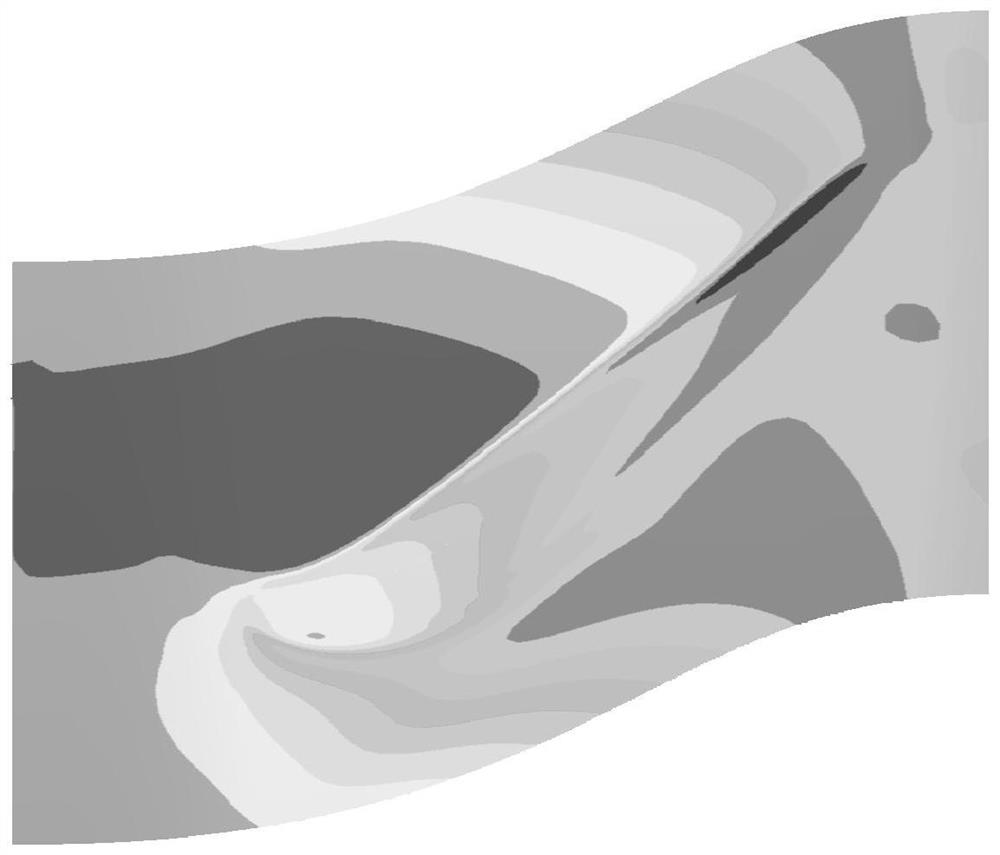
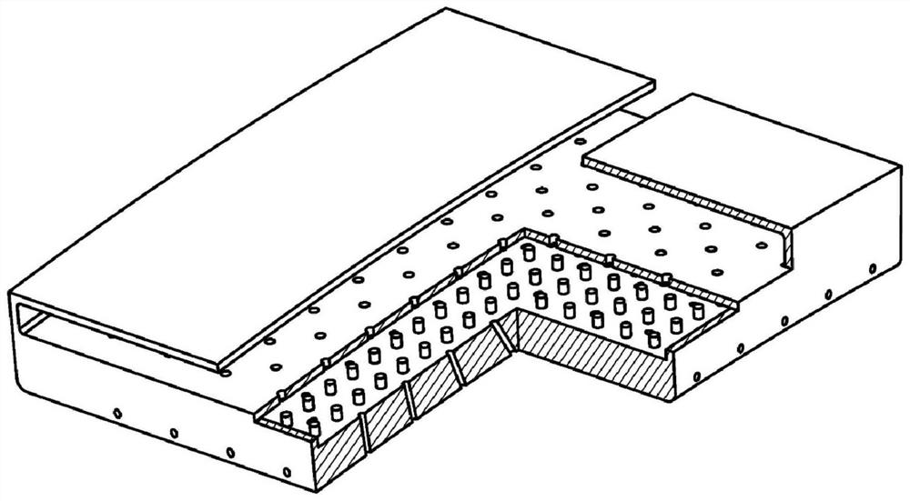
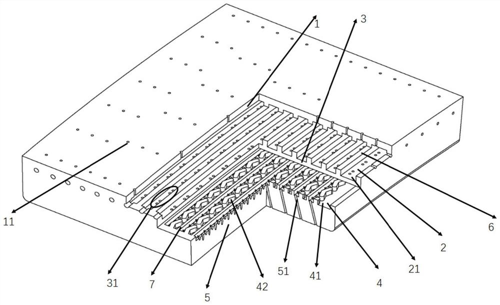
[0004] In order to solve the problem of unreasonable distribution of cold air due to the large axial pressure gradient at the outlet of the outer ring block and the large temperature gradient at the main flow side during the cooling process of the outer ring block, which further affects the cooling of the outer ring block and the excessive loss of cold air, the present invention designs An air supply structure for the turbine outer ring block with precise cavity air supply. By adding a throttle cavity, the existing impact-turbulence-air film composite cooling three-layer structure of the outer ring block is changed to throttling-impact-disturbance Flow-air film composite cooling four-layer structure
The present invention adds a throttling function before the impingement hole, so that the intake and exhaust pressure of impingement-turbulence-air film compound cooling along the axial direction of the turbine can have a tendency to decrease, thereby avoiding the The air intake pressure of the outer ring block is too high, which leads to insufficient cooling caused by the blowing ratio of the air film hole, and the performance degradation caused by the excessive flow rate.

Method used


Image

  • A turbine outer ring block air supply structure with separate chamber air supply
  • A turbine outer ring block air supply structure with separate chamber air supply
  • A turbine outer ring block air supply structure with separate chamber air supply

Examples


Embodiment Construction

[0025] The present invention adds a layer of throttling cavity between the air supply cavity and the impingement cavity of the outer ring block of the turbine, and divides the throttle cavity into a plurality of independent composite cooling throttling sub-cavities along the axial direction of the turbine. Corresponding to the cavity, the impact cavity of composite cooling is also divided into multiple independent impact sub-cavities along the axial direction of the turbine, so that the entire outer ring block is divided into multiple cooling units that do not interfere with each other along the axial direction of the turbine, avoiding the impact caused by a single impact cavity The resulting problem that the outer ring block is poor before cooling and then rich after cooling has formed a targeted cooling structure, which improves the utilization rate of cold air, and then improves the engine performance under the premise of the same temperature before the turbine.

[0026] The...


PUM


Abstract

The invention belongs to the field of thermal protection of aero-engines, and in particular relates to a turbine outer ring block air supply structure for precise cavity-supply air supply. The present invention adds a layer of throttling cavity between the air supply cavity and the impingement cavity of the outer ring block of the turbine, and divides the throttle cavity into a plurality of independent composite cooling throttling sub-cavities along the axial direction of the turbine. Corresponding to the cavity, the impact cavity of composite cooling is also divided into multiple independent impact sub-cavities along the axial direction of the turbine, so that the entire outer ring block is divided into multiple cooling units that do not interfere with each other along the axial direction of the turbine, avoiding the impact caused by a single impact cavity As a result, the outer ring block is poor before cooling and rich after cooling, forming a targeted cooling structure, improving the utilization rate of cold air, and enhancing engine performance at the same time.

Description

technical field [0001] The invention belongs to the field of thermal protection of aero-engines, and in particular relates to a turbine outer ring block air supply structure for precise cavity-supply air supply. Background technique [0002] At present, the temperature before the turbine of the aero-engine has reached about 2000K. According to the thermal cycle, the temperature before the turbine of the aero-engine will continue to increase with the improvement of performance in the future, so the cooling of the outer ring of the turbine is extremely important. The bleed air flow rate of the air system of the existing engine has reached 25%, and it may be higher in the future. The increase of the bleed air flow rate of the air system has greatly inhibited the improvement of engine performance, so how to reduce the bleed air flow rate of the air system has become the hot end of the engine Critical issues in component cooling design. [0003] The outer ring block of the engin...

Claims


Application Information

Patent Timeline
Patent Type & Authority Patents(China)
IPC IPC(8): F01D5/18F01D25/12
CPCF01D5/18F01D5/186F01D5/188F01D25/12
Inventor 邱天丁水汀高自强徐阳刘传凯刘晓静
Owner BEIHANG UNIV
Learn More