
Hydrodynamic cavitation generation device and method

A generation device, a technology of hydraulic cavitation, applied in the direction of mechanical oscillation water/sewage treatment, etc., can solve the problems that occur inside the cavity, difficult to apply material processing, weakened cavitation effect, etc., to achieve high cavitation strength and high pressure. Effect

Active Publication Date: 2021-07-16
CHINA UNIV OF PETROLEUM (EAST CHINA)
View PDF2 Cites 2 Cited by
  • Summary
  • Abstract
  • Description
  • Claims
  • Application Information

AI Technical Summary

Problems solved by technology

[0004] The inventors have found that the current cavitation generating devices combined with orifice plates, orifice plates and Venturi tubes are all based on steady-state cavitation, but as the cavitation progresses, the cavitation effect will be weakened, and the cavitation effect is not good, while The cavitation generated by the existing cavitation device with centrifugal impeller structure occurs inside the cavity, which is difficult to apply to the fields of material processing and other fields

Method used


Image

  • Hydrodynamic cavitation generation device and method
  • Hydrodynamic cavitation generation device and method
  • Hydrodynamic cavitation generation device and method

Examples


Embodiment 1

[0033] This embodiment discloses a hydraulic cavitation generating device. In this embodiment, the steady state refers to the state when the fluid flow velocity is stable, and the unsteady state refers to the state when the fluid flow velocity changes.

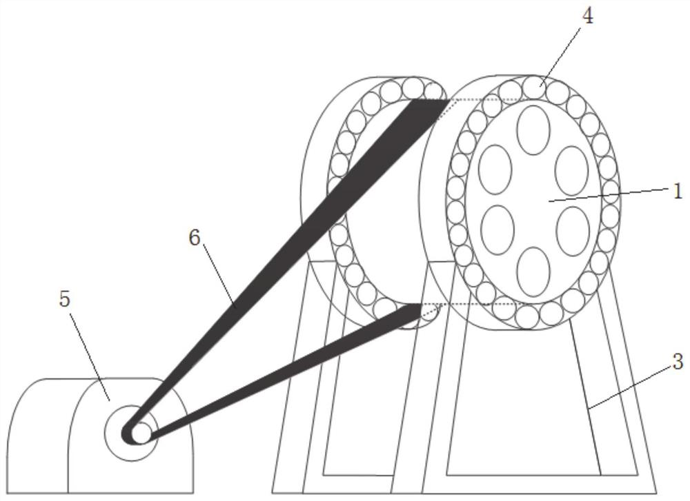
[0034] The hydraulic cavitation generating device of this embodiment includes a wheel disc, a water inlet pipe, a driving mechanism, a water tank and a circulating pump.

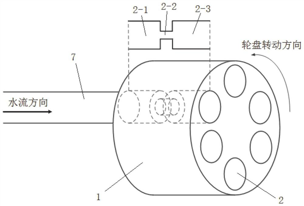
[0035] The wheel disc is a cylindrical disc body structure, and a plurality of flow channels are opened on the wheel disc, and the plurality of flow channels are evenly distributed along the circumference with the center of the wheel disc as the center.

[0036] In this embodiment, six flow channels 2 are provided on the wheel disk 1, and the six flow channels are evenly distributed along the circumference.

[0037] The central part inside the flow channel is provided with an orifice plate, and the orifice plate is provided with a throat hole coaxially arran...

Embodiment 2

[0046] This embodiment discloses a method of the hydraulic cavitation generating device described in Embodiment 1:

[0047] Pour water into the water tank so that the wheel is submerged in the water, start the circulation pump and drive the motor, the wheel rotates, when the flow channel of the wheel is aligned with the water inlet pipe, the static water in the flow channel receives the impact of the water in the water inlet pipe It becomes water flowing according to the set flow rate, realizes unsteady cavitation, and generates cavitation bubbles. When the wheel rotates and the water inlet pipe is aligned with the next flow channel, the water in the next flow channel undergoes unsteady cavitation.

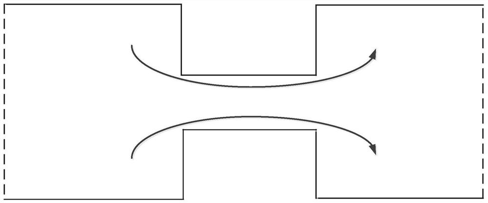
[0048] When the existing orifice plate or the cavitation generating device combined with the orifice plate and the Venturi tube works, such as image 3 As shown, the vortex in the throat of the orifice plate is not obvious when the flow is steady, and even there is no vortex behin...


PUM


Abstract

The invention relates to a hydrodynamic cavitation generation device and method. The device comprises a wheel disc which is provided with a plurality of flow channels, the flow channels being internally provided with pore plates, and the pore plates being provided with throat holes; a driving mechanism connected with the wheel disc and used for driving the wheel disc to rotate; and a water inlet pipe fixedly arranged and attached to the end face of one side of the wheel disc. Water can be injected into the flow channel when the water inlet pipe is aligned with the flow channel, and the hydrodynamic cavitation generation device is good in cavitation effect.

Description

technical field [0001] The invention relates to the technical field of hydraulic cavitation applications, in particular to a hydraulic cavitation generating device and method. Background technique [0002] The statements herein merely provide background information related to the present invention and do not necessarily constitute prior art. [0003] At present, cavitation is gradually playing a role in the fields of sewage treatment, medical treatment, chemistry, and material processing. Compared with laser and ultrasonic cavitation, hydraulic cavitation has the advantages of simple operation and low cost. It is a hot research topic at present. Traditional hydraulic cavitation The generating device adopts orifice plate structure, orifice plate and Venturi tube combined structure or centrifugal impeller structure. [0004] The inventors have found that the current cavitation generating devices combined with orifice plates, orifice plates and Venturi tubes are all based on s...

Claims


Application Information

Patent Timeline
Patent Type & Authority Applications(China)
IPC IPC(8): C02F1/34
CPCC02F1/34B01F27/25B01F25/4335B01F2025/911B01F2025/931B01F23/232
Inventor 刘翠伟李雪洁冯庆善李玉星廖艺涵尹渊博崔兆雪肖康杨宏超丁锐
Owner CHINA UNIV OF PETROLEUM (EAST CHINA)
Learn More