
Cement production carbon capture device and process for local calcium circulation coupling waste disposal

A technology of waste and calcium cycle, applied in the intersection of calcium cycle carbon capture and co-processing of solid waste, in the field of cement production, can solve the problems of concentration decrease, CaO carbon fixation activity decrease, increase the difficulty of purification and capture, etc. Achieve the effects of reducing difficulty, increasing concentration, and improving capture rate and efficiency

Pending Publication Date: 2021-07-16
SOUTH CHINA UNIV OF TECH
View PDF8 Cites 1 Cited by
  • Summary
  • Abstract
  • Description
  • Claims
  • Application Information

AI Technical Summary

Problems solved by technology

Due to the abundant presence of CaO in cement kilns, calcium cycling has the potential to achieve high-efficiency carbon capture, but the carbon fixation activity of CaO decreases significantly after multiple cycles, and the SO released from the decomposition of sulfide during raw meal preheating 2 Will participate in the gas circulation of the cement kiln system, resulting in CO in the flue gas 2 The concentration of the concentration decreases, which greatly increases the difficulty of the tail end treatment and capture of cement kiln flue gas
In addition, the temperature of flue gas at the kiln tail in the new dry process cement kiln system is as high as about 1200 °C, which is significantly higher than that of CaCO 3 The decomposition temperature significantly reduces the CaO cycle to capture CO 2 Capacity and efficiency; NOx produced during fuel combustion also increases CO 2 The difficulty of purification and capture ultimately hinders the promotion and application of local calcium circulation technology in the field of carbon capture from cement kiln flue gas

Method used


Image

  • Cement production carbon capture device and process for local calcium circulation coupling waste disposal

Examples


Embodiment Construction

[0038] This part will describe the specific embodiment of the present invention in detail, and the preferred embodiment of the present invention is shown in the accompanying drawings. Each technical feature and overall technical solution of the invention, but it should not be understood as a limitation on the protection scope of the present invention.

[0039] In the description of the present invention, it should be understood that the orientation descriptions, such as up, down, front, back, left, right, etc. indicated orientations or positional relationships are based on the orientations or positional relationships shown in the drawings, and are only In order to facilitate the description of the present invention and simplify the description, it does not indicate or imply that the device or element referred to must have a specific orientation, be constructed and operated in a specific orientation, and thus should not be construed as limiting the present invention.

[0040] I...


PUM


Abstract

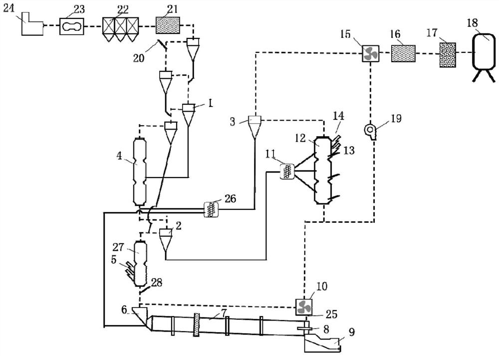
The invention discloses a cement production carbon capture device and process for local calcium circulation coupling waste disposal, and belongs to the cross technical field of cement production, calcium cycle carbon capture and waste co-disposal. The cement production carbon capture device consists of an off-line decomposing furnace module, a preheater-carbonization furnace-rotary kiln module and an auxiliary and purification device. According to the carbon capture process, CO2 capture is completed by means of CaO-CaCO3-CaO circulation between a decomposing furnace and a carbonization furnace, the off-line decomposing furnace design is adopted, and SO2, chlor-alkali sulfur and other impurities generated in the clinker sintering and raw material preheating process are prevented from entering a decomposing furnace module. Meanwhile, waste is combined for cooperative treatment, the flue gas temperature is lowered, the CaO carbon sequestration rate and efficiency are improved, NOx generated by the rotary kiln is reduced through waste thermal cracking products, flue gas CO2 self-enrichment and multi-pollutant cooperative control under the air combustion condition are achieved, the follow-up CO2 purification and recycling difficulty is lowered, the technical economy is remarkably improved, and the popularization of carbon capture and recycling of the cement industry is powerfully promoted.

Description

technical field [0001] The invention relates to the interdisciplinary technical field of cement production, calcium cycle carbon capture and solid waste co-processing, in particular to a cement production carbon capture device and process for local calcium cycle coupling waste disposal. Background technique [0002] With the rapid development of the national economy, China's CO 2 Emissions are increasing year by year, reaching 9.43 billion tons in 2017, of which the cement industry is my country's CO2 2 One of the main emission sources (annual emission is about 2 billion tons, accounting for about 21%). Therefore, my country is under great pressure to reduce carbon emissions, and it is particularly important and urgent to reduce carbon emissions in the cement industry. [0003] Carbon emission reduction in the cement industry is mainly achieved through flue gas purification and capture. At present, the main capture processes include: chemical absorption method, membrane se...

Claims


Application Information

Patent Timeline
IPC IPC(8): C01B32/50C04B7/36
CPCC01B32/50C04B7/367Y02P20/129
Inventor 张同生汪伟郭奕群韦江雄余其俊
Owner SOUTH CHINA UNIV OF TECH
Learn More