
Light-transmitting pressing plate, welding fixture, welding device and welding method of welding device

A welding fixture and welding device technology, applied in the fields of welding fixtures, light-transmitting platens, and welding devices, can solve problems such as fragile, unprocessable, and difficult to process, and achieve the purpose of ensuring service life, improving production efficiency, and improving final quality. Effect

Pending Publication Date: 2021-07-16
HANS LASER TECH IND GRP CO LTD
View PDF4 Cites 0 Cited by
  • Summary
  • Abstract
  • Description
  • Claims
  • Application Information

AI Technical Summary

Problems solved by technology

These methods have obvious disadvantages: transparent acrylic has a low melting point, and the heat generated by the laser is easy to melt and damage the acrylic, which needs to be replaced regularly; brittle materials such as transparent glass have a high melting point but are not easy to process, and samples with complex welding tracks cannot be processed. And it is relatively easy to break, and it needs to be replaced regularly; using metal as a pressure plate will easily cause warping and deformation in the middle of the upper part, which will affect the final quality of welding

Method used


Image

  • Light-transmitting pressing plate, welding fixture, welding device and welding method of welding device
  • Light-transmitting pressing plate, welding fixture, welding device and welding method of welding device
  • Light-transmitting pressing plate, welding fixture, welding device and welding method of welding device

Examples


Embodiment Construction

[0043] In order to facilitate the understanding of the present invention, the present invention will be described more fully below with reference to the associated drawings. Preferred embodiments of the invention are shown in the accompanying drawings. However, the present invention is capable of being implemented in many different forms and is not limited to the embodiments described herein. On the contrary, these embodiments are provided to make the understanding of the disclosure of the present invention more thorough and comprehensive.

[0044] It should be noted that when an element is referred to as being “fixed” to another element, it can be directly on the other element or there can also be an intervening element. When an element is referred to as being "connected to" another element, it can be directly connected to the other element or intervening elements may also be present. The terms "vertical," "horizontal," "left," "right," and similar expressions are used here...


PUM


Abstract

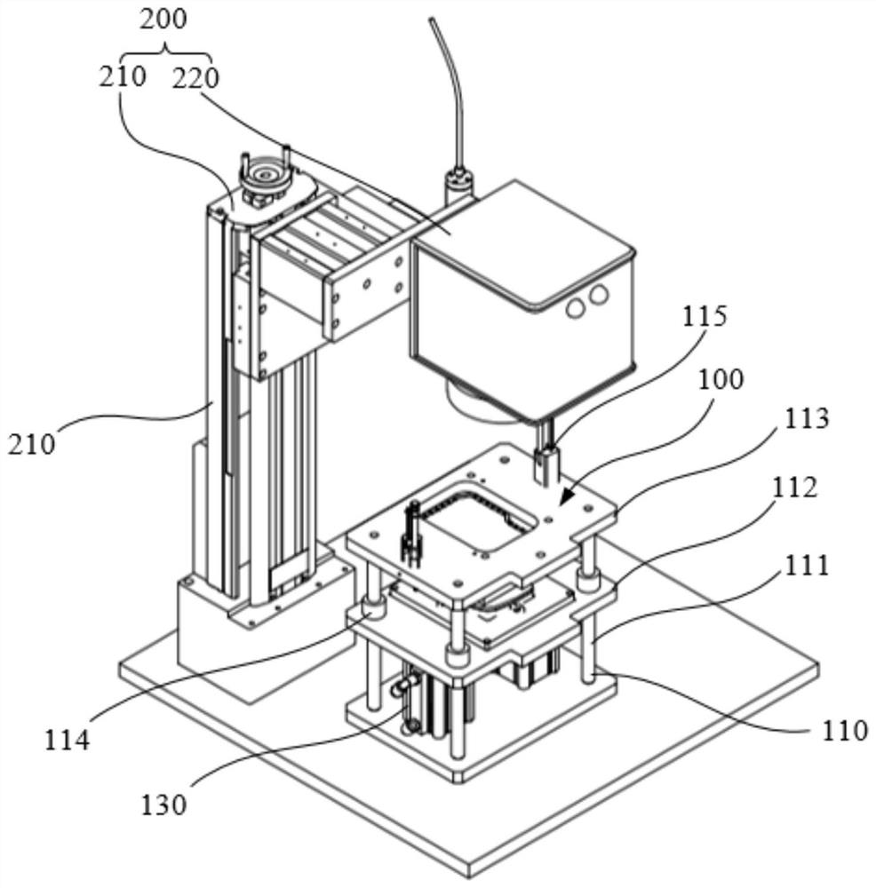
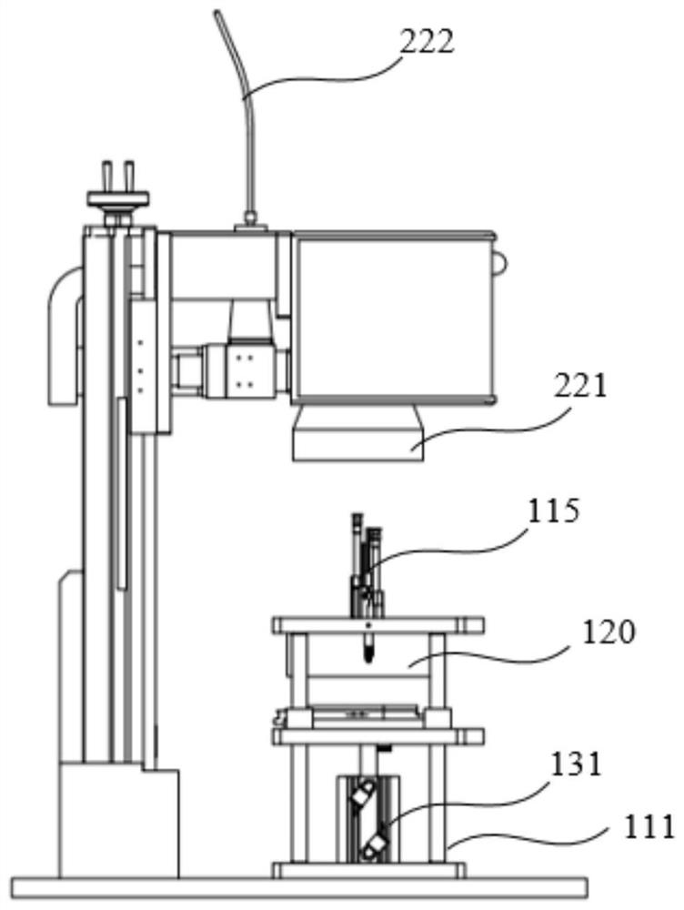
The invention discloses a light-transmitting pressing plate, a welding fixture, a welding device and a welding method of the welding device. The light-transmitting pressing plate comprises an outer peripheral pressing plate, an inner peripheral pressing plate and connecting ribs, wherein the outer peripheral pressing plate defines a mounting area; the inner peripheral pressing plate is arranged in the mounting area; a hollow area which has a predetermined depth and can allow laser to pass through is formed between the inner peripheral pressing plate and the outer peripheral pressing plate; and the connecting ribs are connected between the outer peripheral pressing plate and the inner peripheral pressing plate, and used for connecting the outer peripheral pressing plate and the inner peripheral pressing plate into a whole. The service life of the light-transmitting pressing plate can be guaranteed, the light-transmitting pressing plate does not need to be replaced, cost is reduced, and production efficiency is improved; meanwhile, due to the fact that the outer peripheral pressing plate and the inner peripheral pressing plate are connected into a whole through the connecting ribs, the contact area between the light-transmitting pressing plate and a to-be-welded part can become larger, uniform and good pressing force can be easily generated, and the final welding quality can be improved.

Description

technical field [0001] The invention relates to the field of welding technology, in particular to a light-transmitting press plate, a welding jig, a welding device and a welding method thereof. Background technique [0002] At present, the laser welding of thermoplastics adopts the principle of transmission welding, that is, the two parts to be welded are overlapped and placed together, the upper part can pass through the laser and the lower part must be able to absorb the laser, and then form on the contact surface (welding area) of the two parts. In the heat action zone, the plastic in the heat action zone is melted, and the molecules of the plastic in the molten state diffuse each other under the action of pressure, resulting in van der Waals force, so that the two pieces are closely connected together, so that the melted material A joint is formed and the parts to be welded are joined. [0003] When using the above welding method for sealing welding (the welding track i...

Claims


Application Information

Patent Timeline
IPC IPC(8): B29C65/16B29C65/78
CPCB29C65/1635B29C65/7841
Inventor 苏长鹏刘维波黄裕佳王瑾高云峰
Owner HANS LASER TECH IND GRP CO LTD
Learn More