


Quick Research
Generate reliable direction feasibility study reports for your R&D in just a few steps.

Technical Q&A
Discover and master advanced knowledge NOW. Basics, ideas, possibilities, all at once.

Find Solutions
As an expert in R&D theories, this can generate solutions to your technical problems instantly.

Evaluate Feasibility
Analyze your overall solution with one click, know your potential R&D risks in advance.

Monitor Landscape
Get weekly tech updates, stay abreast of the latest tech innovations and key insights.
Efficient heat dissipation device for air compressor
A technology of heat dissipation device and air compressor, which is used in electromechanical devices, cooling/ventilation devices, mechanical equipment, etc. Effect
- Summary
- Abstract
- Description
- Claims
- Application Information
AI Technical Summary
Problems solved by technology
Method used
Image

Examples
Embodiment 1
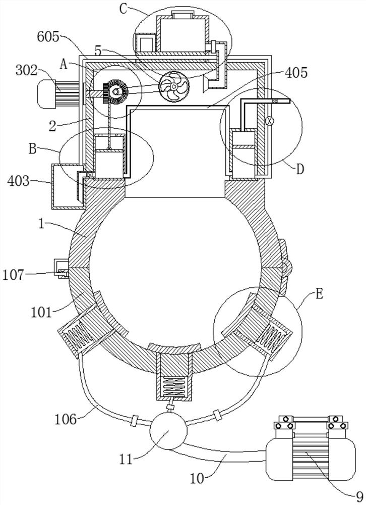
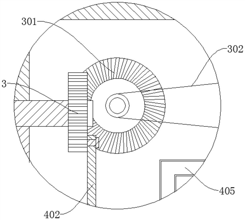
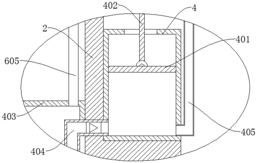
[0036] refer to Figure 1-6, a high-efficiency heat dissipation device for an air compressor, comprising a first fixed sleeve 1, a second fixed sleeve 101, and a heat dissipation box 2, the heat dissipation box 2 is fixedly connected to the side wall of the first fixed sleeve 1, the second fixed sleeve 101 and the second fixed sleeve A fixed sleeve 1 is connected by a hinge, and the end of the first fixed sleeve 1 and the second fixed sleeve 101 away from the hinge is connected by a lock 107. The side wall of the cooling tank 2 is provided with a first water tank 403, and the cooling tank 2 rotates inside The gear part 3 and the bevel gear 301 are connected, the bevel gear 301 is meshed with the gear part 3, the side wall of the cooling box 2 is provided with a motor 303, the output end of the motor 303 is fixedly connected with the gear part 3, and the gear part 3 is connected with a push Rod 402, the cooling box 2 is provided with a pumping tank 4, a piston 401 is slidably c...
Embodiment 2
[0039] refer to Figure 1-6 , a high-efficiency heat dissipation device for an air compressor, which is basically the same as in Example 1. Further, the refrigerant is preferably a solid carbon dioxide block, which is also called dry ice, which is non-toxic, has no impact on the ozone layer, and does not produce a greenhouse effect. and good thermodynamic properties.
Embodiment 3
[0041] refer to Figure 1-6 , a high-efficiency heat dissipation device for an air compressor, which is basically the same as that of Embodiment 1. Further, the second fixed sleeve 101 is provided with multiple groups of chute 102, and the chute 102 is slidably connected with a sliding rod 103, and the sliding One end of the bar 103 located outside the chute 102 is fixedly connected with a clamping plate 104, one end of the slide bar 103 located in the chute 102 is fixedly connected with a spring 105, and the end of the spring 105 away from the slide bar 103 is fixedly connected to the inner wall of the chute 102, The air delivery pipe 106 is connected to the chute 102, and the air distribution valve 11 is connected to the end of the multi-group air delivery pipe 106 away from the chute 102, the gas distribution valve 11 is connected to the conduit 10, and the air pump 9 is connected to the end of the conduit 10 away from the air distribution valve 11 At the output end of the ...
PUM
 Abstract
Description
Claims
Application Information
 - R&D Engineer
- R&D Manager
- IP Professional
- Industry Leading Data Capabilities
- Powerful AI technology
- Patent DNA Extraction
Browse by: Latest US Patents, China's latest patents, Technical Efficacy Thesaurus, Application Domain, Technology Topic, Popular Technical Reports.
© 2024 PatSnap. All rights reserved.Legal|Privacy policy|Modern Slavery Act Transparency Statement|Sitemap|About US| Contact US: help@patsnap.com