
Quick propeller mounting mechanism for multi-rotor aircraft

A technology of multi-rotor aircraft and mounting mechanism, which is applied in the direction of rotorcraft, aircraft, unmanned aircraft, etc., can solve the problems of motor output shaft damage, low assembly stability, large volume and weight of fixed base, etc., and achieve reduction The effect of difficulty of operation, reduction of volume and weight, and improvement of convenience

Active Publication Date: 2021-07-13
厦门致睿智控地信科技股份有限公司
View PDF7 Cites 0 Cited by
  • Summary
  • Abstract
  • Description
  • Claims
  • Application Information

AI Technical Summary

Problems solved by technology

Although the intervention of the quick installation mechanism can effectively realize the quick disassembly and assembly of the propeller, compared with the fixed locking method, its assembly stability is relatively low
In order to ensure the assembly of the propeller and the stability of its operation, the connecting parts are generally fixed and mounted on the fixed base by means of mounting. The corresponding clamping parts / clamping grooves fix the connecting parts, resulting in a relatively large volume and weight of the fixed base
After the propeller is disassembled, the fixed base with large volume and weight is still fixed on the output shaft end of the motor of the aircraft. , During transportation, etc., it is easy to cause damage to the output shaft of the motor

Method used


Image

  • Quick propeller mounting mechanism for multi-rotor aircraft
  • Quick propeller mounting mechanism for multi-rotor aircraft
  • Quick propeller mounting mechanism for multi-rotor aircraft

Examples


Embodiment Construction

[0041] In order to facilitate the understanding of those skilled in the art, the structure of the present invention will be further described in detail with the embodiments in conjunction with the accompanying drawings:

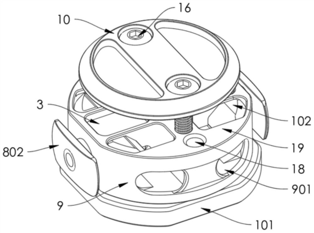
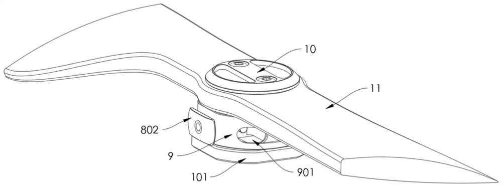
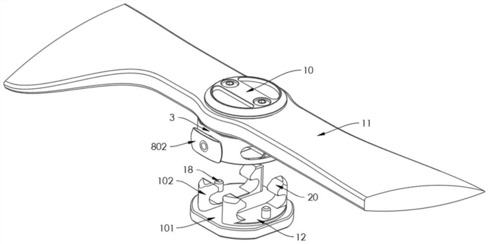
[0042] refer to Figure 1-8 , a fast propeller installation mechanism for a multi-rotor aircraft, comprising

[0043] The fixed base 1 includes a base plate 101 fixedly connected to the output shaft end of the motor and two sets of fasteners 102 arranged on the base plate 101, and the opposite sides of the same set of fasteners 102 are respectively provided with corresponding fastening grooves 2;

[0044] The connecting piece 3 is detachably mounted on the fixed base 1, and the connecting piece 3 is respectively provided with a corresponding chute 4 at a position corresponding to the buckling groove 2, and the connecting piece 3 is mounted on the chute The outer sides of 4 are respectively provided with corresponding mounting holes 5, and corresponding faste...


PUM


Abstract

The invention relates to a quick propeller mounting mechanism for a multi-rotor aircraft, which comprises a fixed base, wherein the fixed base comprises a base plate and at least one group of fasteners arranged on the base plate, and the opposite sides of the same group of fasteners are respectively provided with corresponding fastening grooves; connecting pieces, wherein corresponding sliding grooves are formed in the positions, corresponding to the buckling grooves, of the connecting pieces respectively, corresponding mounting holes are formed in the positions, on the outer sides of the sliding grooves, of the connecting pieces respectively, corresponding buckling shafts are movably mounted in the sliding grooves respectively, and the buckling shafts are detachably buckled in the corresponding buckling grooves respectively; a pressing mechanism which comprises mounting parts, wherein the inner ends of the mounting parts penetrate through the corresponding mounting holes and then are connected to the corresponding buckling shafts respectively; a reinforcing plate, the sides, not provided with the buckling grooves, of the fasteners abut against the inner sides of the reinforcing plates respectively; and a fixed connection cover plate used for connecting a propeller to the connecting piece. Assembly and operation stability of the propeller can be ensured, and the size and weight of the fixing base can be reduced.

Description

technical field [0001] The invention relates to a quick installation mechanism for a propeller of a multi-rotor aircraft, which is mainly used for quick installation of the propeller for a multi-rotor aircraft. Background technique [0002] A multi-rotor aircraft refers to a special flight device with three or more rotor shafts, which is equipped with a motor on each shaft to drive the propeller (rotor) through transmission to generate lift. The propellers used in traditional multi-rotor aircraft are generally fixed and locked to the output shaft end of the motor. In order to improve the convenience of use, most of the existing propellers for multi-rotor aircraft adopt a quick installation mechanism, which is detachably connected to the output shaft end of the corresponding motor. [0003] Existing propeller rapid installation mechanisms for multi-rotor aircraft generally include a fixed base fixed to the output shaft end of the motor and a connector detachably mounted on t...

Claims


Application Information

Patent Timeline
Patent Type & Authority Applications(China)
IPC IPC(8): B64C27/14B64C27/32B64D27/26B64D27/40
CPCB64C27/14B64C27/32B64U50/19B64U10/10B64D27/40Y02T50/40
Inventor 李震灏陈阳杨伟
Owner 厦门致睿智控地信科技股份有限公司
Learn More