Evaporative Cooling Logic Control Method for Inductive Vibration Equipment

A vibration equipment, evaporative cooling technology, applied in electrical equipment structural parts, cooling/ventilation/heating renovation, electrical components, etc., can solve the problems of reducing cooling air flow, affecting cooling efficiency, increasing wind pressure, etc. The effect of radial expansion, reliable function and simple structure

Active Publication Date: 2022-06-17
6 DOF VIBRATION TESTING DEVICE WITH ELECTRODYNAMIC EXCITATION +1
View PDF5 Cites 0 Cited by
  • Summary
  • Abstract
  • Description
  • Claims
  • Application Information

AI Technical Summary

Problems solved by technology

[0005] The existing induction ring forms corresponding vibrations under the action of the static magnetic field, but the lower induction ring generates an induction current, so the surface temperature will also increase accordingly, and the radial expansion of the induction ring increases. With the increase of expansion, the original moving gas The air gap will be reduced accordingly. In the process of fan cooling and exhaust cooling, the original cooling air flow through the surface of the induction ring will be reduced and the wind pressure will be increased, which will affect the cooling efficiency. In order to take away the heat of the induction ring as soon as possible, high efficiency is still required. The evaporative cooling logic control method, through the spray (liquid nitrogen) cooling device, sprays a small amount of atomized distilled water vapor on its surface, so that the heat generated on the surface is quickly vaporized and evaporated, and then the latent heat is taken away by the air flow, thereby controlling the heating of the induction ring The final radial expansion size can improve the heat dissipation effect and improve the trouble-free working time of vibration equipment. Therefore, a new type of evaporative cooling control logic method is needed to solve the existing problems.

Method used


Image

  • Evaporative Cooling Logic Control Method for Inductive Vibration Equipment
  • Evaporative Cooling Logic Control Method for Inductive Vibration Equipment

Examples


Embodiment Construction

[0028] The present invention will be further described below in conjunction with the accompanying drawings:

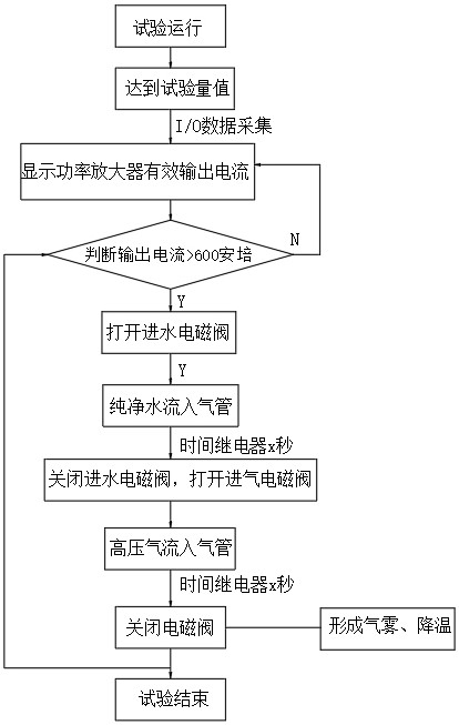
[0029] Logic control method for evaporative cooling of induction vibration equipment, which includes the following steps:

[0030] (1) Test run:

[0031] Step 1: Turn on the vibration device and collect data;

[0032] Step 2: The power amplifier displays the effective output current, and judges whether the effective output current is greater than 600 amperes;

[0033] (2) When the effective output current is greater than 600 amperes:

[0034] Step 1: Open the water inlet solenoid valve, the time relay performs automatic timing, and pure water flows into the air pipe;

[0035] Step 2: When the water intake time is up, close the water intake solenoid valve, open the intake solenoid valve, the intake relay will automatically time the time, and the high-pressure air flow enters the trachea. After the time is up, close the intake solenoid valve;

[0036] Step 3: The hig...


PUM


Abstract

The invention discloses a logical control method for evaporative cooling of an inductive vibration device, which comprises the following steps: step 1: turn on the vibration device and collect data; step 2: a power amplifier displays an effective output current, and judges whether the effective output current is greater than 600 amperes. The beneficial effect is that: the spray-assisted cooling mode of the inductive vibration equipment adjusted by the logic control method of the present invention has a simple structure and reliable function, and can effectively solve the phenomenon that the induction ring traditional fan has insufficient ventilation and heat dissipation capacity, and reduces its radial expansion, which is especially suitable for It is suitable for the heat dissipation of the induction ring of the large and medium thrust induction vibration equipment with a large induction ring current.

Description

technical field [0001] The present invention relates to the field of methods for cooling and cooling the interior of an inductive vibrating table, and relates to an evaporative cooling logic control method for inductive vibrating equipment. Background technique [0002] The electric vibration table is the key test equipment necessary for the development of aerospace (military) products such as rockets, missiles, and satellites. The development of products in various industries such as trains and the verification of products under simulated working conditions. Domestic and foreign suppliers of vibration test equipment mostly use a directly coupled shaking table to generate exciting force to achieve vibration, and its operating frequency is 5-2000HZ; the maximum frequency sweep acceleration is generally 100G; the random no-load acceleration is generally 80G, which cannot meet the (military) civilian requirements The product's requirements for test equipment and continuously i...

Claims


Application Information

Patent Timeline
Patent Type & Authority Patents(China)
IPC IPC(8): H05K7/20
CPCH05K7/20345H05K7/20327H05K7/20381G01M7/02
Inventor 秦亚明张奎华张巧寿张红彩陈晨田看丽
Owner 6 DOF VIBRATION TESTING DEVICE WITH ELECTRODYNAMIC EXCITATION
Why Eureka
Try Eureka