Logical control method for evaporative cooling of inductive type vibration equipment

A vibrating equipment and evaporative cooling technology, which is applied to the structural parts of electrical equipment, cooling/ventilation/heating transformation, electrical components, etc., can solve the problems of cooling air flow reduction, affecting cooling efficiency, and increasing wind pressure, etc., to achieve reduction The effect of radial expansion, reliable function and simple structure

Active Publication Date: 2021-07-09
6 DOF VIBRATION TESTING DEVICE WITH ELECTRODYNAMIC EXCITATION +1
View PDF5 Cites 2 Cited by
  • Summary
  • Abstract
  • Description
  • Claims
  • Application Information

AI Technical Summary

Problems solved by technology

[0005] The existing induction ring forms corresponding vibrations under the action of the static magnetic field, but the lower induction ring generates an induction current, so the surface temperature will also increase accordingly, and the radial expansion of the induction ring increases. With the increase of expansion, the original moving gas The air gap will be reduced accordingly. In the process of fan cooling and exhaust cooling, the original cooling air flow through the surface of the induction ring will be reduced and the wind pressure will be increased, which will affect the cooling efficiency. In order to take away the heat of the induction ring as soon as possible, high efficiency is still required. The evaporative cooling logic control method, through the spray (liquid nitrogen) cooling device, sprays a small amount of atomized distilled water vapor on its surface, so that the heat generated on the surface is quickly vaporized and evaporated, and then the latent heat is taken away by the air flow, thereby controlling the heating of the induction ring The final radial expansion size can improve the heat dissipation effect and improve the trouble-free working time of vibration equipment. Therefore, a new type of evaporative cooling control logic method is needed to solve the existing problems.

Method used


Image

  • Logical control method for evaporative cooling of inductive type vibration equipment
  • Logical control method for evaporative cooling of inductive type vibration equipment

Examples


Embodiment Construction

[0028] The present invention will be further described below with reference to the accompanying drawings:

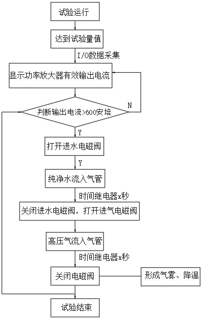
[0029] Induction Vibration Equipment Evaporative Cooling Logic Control Method, which includes the following steps:

[0030] (1) Test operation:

[0031] Step 1: Turn on the vibration device to collect data;

[0032] Step 2: The power amplifier displays the effective output current and determines whether the effective output current is greater than 600 amps;

[0033] (2) Effective output current is greater than 600 amps:

[0034] Step 1: Open the water solenoid valve, the time relay is automatically timed, pure water flows into the trachea;

[0035] Step 2: After the water supply time is reached, turn off the water solenoid valve, open the intake solenoid valve, the intake relay automatically time, the high pressure air flow enters the trachea, and the intake electromagnetic valve is turned off.

[0036] Step 3: The high pressure gas flow in the trachea can spray pure water, ...


PUM


Abstract

The invention discloses a logic control method for evaporative cooling of inductive type vibration equipment. The method comprises the following steps: 1, starting vibration equipment, and acquiring data; and 2, enabling a power amplifier to display the effective output current, and judging whether the effective output current is larger than 600 amperes or not. The the logic control method for adjusting the inductive type vibration equipment by a spray auxiliary cooling method has the beneficial effects that the structure is simple, the function is reliable, the phenomenon that a traditional fan of an induction ring is insufficient in air draft and heat dissipation capacity can be effectively solved, radial expansion is reduced, and the method is especially suitable for heat dissipation of the induction ring of large and medium thrust inductive type vibration equipment with large induction ring current.

Description

Technical field [0001] The present invention relates to the field of internal cooling cooling of the inductive vibrating table, and the present invention relates to an inductive vibration device evaporative cooling logic control method. Background technique [0002] The electric vibrating table is a key test equipment that must be developed by Rockets, missiles, satellites and other space (military) products. It is widely used in product strength check, transportation environment testing, reliability and other experiments, involving aerospace, aviation, ship, car, The development of various industries such as trains and the product of the product under the environment of the simulation. Domestic and foreign vibration test equipment provides exclusive vibration to generate vibration, operating frequency of 5-2000 Hz; maximum sweep acceleration is generally 80g, and the random air-load acceleration is generally 80g, and cannot meet (military) people Products on test equipment and c...

Claims


Application Information

Patent Timeline
Patent Type & Authority Applications(China)
IPC IPC(8): H05K7/20
CPCH05K7/20345H05K7/20327H05K7/20381G01M7/02
Inventor 秦亚明张奎华张巧寿张红彩陈晨田看丽
Owner 6 DOF VIBRATION TESTING DEVICE WITH ELECTRODYNAMIC EXCITATION
Why Eureka
Try Eureka