Digital accurate three-phase synchronous signal acquisition and phase shift triggering method

A phase-shift triggering, three-phase synchronization technology, applied in the output power conversion device, electrical components and other directions, can solve the problems of poor phase-shift accuracy, poor phase-shift accuracy, poor three-phase unbalance, and high on-site failure rate. Increased reliability, good parameter consistency, and high triggering accuracy

Active Publication Date: 2021-07-09
岳阳东瑞电气有限公司
View PDF5 Cites 0 Cited by
  • Summary
  • Abstract
  • Description
  • Claims
  • Application Information

AI Technical Summary

Problems solved by technology

First, the analog circuit is susceptible to errors caused by external interference, and the phase shift accuracy and three-phase unbalance are poor, resulting in increased harmonics and aggravating pollution to the power grid; second, due to the poor phase shift accuracy, in some pairs of voltage stability The use occasions with high requirements for high precision can no longer meet the requirements; third, the protection measures are lacking, and the on-site failure rate is high
[0004] In addition, the existing digital phase-shift trigger circuit is implemented by logic circuits such as FPGA or CPLD, which can only realize basic logic control functions and cannot adapt to changes in power grid frequency. It does not use complex parameter calculations and flexible implementation of various protection measures. high failure rate

Method used


Image

  • Digital accurate three-phase synchronous signal acquisition and phase shift triggering method
  • Digital accurate three-phase synchronous signal acquisition and phase shift triggering method
  • Digital accurate three-phase synchronous signal acquisition and phase shift triggering method

Examples


Embodiment Construction

[0022] The following will clearly and completely describe the technical solutions in the embodiments of the present invention with reference to the accompanying drawings in the embodiments of the present invention. Obviously, the described embodiments are only some of the embodiments of the present invention, not all of them.

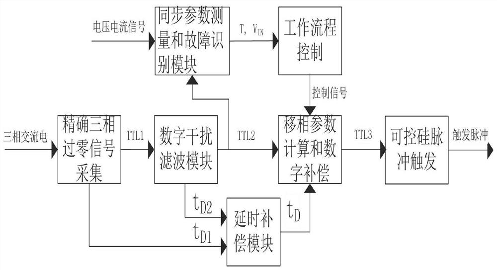
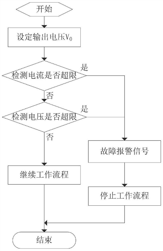
[0023] A digital accurate three-phase synchronous signal acquisition and phase-shift trigger method, including a digital accurate three-phase zero-crossing signal acquisition module, a digital interference filter module, a delay compensation module, a synchronization parameter measurement and fault identification module, and a workflow control module, phase shift parameter calculation and digital compensation module, thyristor pulse trigger module and so on.

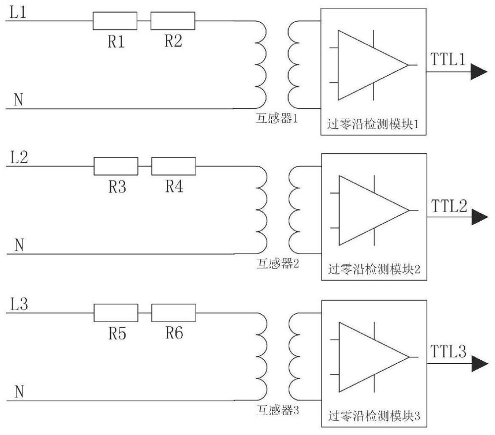
[0024] The accurate three-phase zero-crossing signal acquisition module obtains the TTL level corresponding to the AC zero-crossing point by the precise zero-crossing detection circuit conversion c...


PUM


Abstract

The invention discloses a digital accurate three-phase synchronous signal acquisition and phase shift triggering method. An accurate three-phase zero-crossing signal acquisition module acquires a zero-crossing synchronous signal from a three-phase alternating current; a digital interference filtering module carries out interference filtering on the zero-crossing synchronization signal; a time delay compensation module compensates time delays generated in the signal processing process of the three-phase zero-crossing signal acquisition module and the interference filtering module; a synchronous parameter measurement and fault identification module is used for measuring a power frequency period and voltage and current parameters and identifying fault signals such as a phase loss, a short circuit and the like; a workflow control module controls the workflow and the time sequence of excitation, demagnetization and the like of an electric control system; a phase shift parameter calculation and digital compensation module calculates a trigger time parameter; and a silicon controlled pulse trigger module controls trigger pulse output according to the trigger time parameter. According to the invention, a digital synchronous signal acquisition and filtering method is adopted so that the trigger precision is high and the parameter consistency is good; a digital de-jitter method is adopted to eliminate the influence of interference signals such as burrs on zero-crossing signal detection; and reliability of a working circuit is increased for starting detection, silicon controlled trigger output protection and other circuits in the loading starting process of a load.

Description

technical field [0001] The invention relates to the technical field of electrical automation, in particular to a digital accurate three-phase synchronous signal acquisition and phase-shift triggering method. Background technique [0002] Electromagnets and their associated electronic control systems are widely used. This type of electronic control system generally uses an analog circuit based on a small-scale integrated chip to realize synchronous signal acquisition and phase-shift triggering. This type of circuit converts the signal sent by the synchronous transformer into a sawtooth wave signal, and then compares it with a given DC voltage. The phase-shifting signal is obtained. Since the slope, duty cycle and amplitude of the three-phase sawtooth wave signal are closely related to the parameters of the separated components, the comparison circuit is prone to errors caused by external interference, and the phase-shifting accuracy and three-phase unbalance are poor, resulti...

Claims


Application Information

Patent Timeline
IPC IPC(8): H02M1/06H02M1/44
CPCH02M1/06H02M1/44
Inventor 王益明王贤辉
Owner 岳阳东瑞电气有限公司
Why Eureka
Try Eureka