
A Method of Improving the Trigger Accuracy of Peak Power Measurement

A technology of peak power and accuracy, which is applied in the field of improving the trigger accuracy of peak power measurement, can solve the problems of relatively high requirements, low trigger accuracy, time-consuming and laborious, etc., and achieve the effect of improving personnel efficiency and high trigger accuracy

Active Publication Date: 2021-09-03
CHINA ELECTRONIS TECH INSTR CO LTD
View PDF11 Cites 0 Cited by
  • Summary
  • Abstract
  • Description
  • Claims
  • Application Information

AI Technical Summary

Problems solved by technology

[0005] Using manual calibration and two-point interpolation algorithm is not only inefficient, time-consuming and laborious, but also the trigger accuracy of the entire trigger dynamic range can only be controlled within ±2dB
[0006] Due to the low trigger accuracy, the above scheme cannot satisfy the systems and equipment with frequent pulse envelope signal fluctuations and high requirements for real-time measurement stability.

Method used


Image

  • A Method of Improving the Trigger Accuracy of Peak Power Measurement

Examples


Embodiment Construction

[0029] Below in conjunction with accompanying drawing and specific embodiment the present invention is described in further detail:

[0030] The present invention needs to solve two problems:

[0031] (1) Automatic calibration of the trigger circuit;

[0032] (2) Interpolation algorithm of multiple power points.

[0033] Since the trigger dynamic range of the peak power probe is [-20dBm, 20dBm], the present invention selects 9 power points (-20dBm, -15dBm, -10dBm, -5dBm, 0dBm, 5dBm, 10dBm, 15dBm, 20dBm) for automatic calibration and Interpolation algorithm.

[0034] 1. Automatic calibration of the trigger circuit

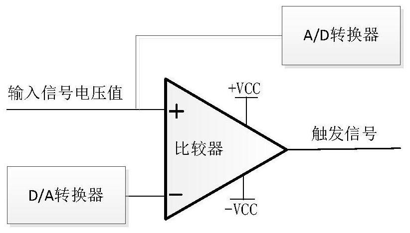
[0035] figure 1 Shown is a schematic diagram of the trigger circuit. The voltage value of the input signal refers to the voltage value before the input power enters the A / D converter and comparator after detection, amplification, filtering, and zero adjustment.

[0036] The automatic calibration process of the trigger circuit is as follows (N takes 9):

[0037...


PUM


Abstract

The invention discloses a method for improving the triggering accuracy of peak power measurement and belongs to the field of peak power measurement. Through the automatic calibration of the trigger circuit and the interpolation algorithm of multiple power points, the method of the present invention can improve the trigger accuracy of the entire trigger dynamic range to within ±0.5dB, ensuring accurate and stable trigger pulse envelopes in the microwave peak power measurement process Signal; the automatic calibration of the trigger circuit improves the efficiency of personnel; the trigger accuracy is increased from within ±2dB to within ±0.5dB, which is increased by 4 times, and the trigger accuracy is higher.

Description

technical field [0001] The invention belongs to the field of peak power measurement, and in particular relates to a method for improving the triggering accuracy of peak power measurement. Background technique [0002] When performing peak power measurement, it is necessary to stably trigger to the pulse envelope signal. At present, analog circuits are used for triggering. In order to ensure trigger accuracy, calibration and compensation of analog trigger circuits are required. [0003] Since the current calibration and compensation of the trigger circuit is manual, and only the linear interpolation algorithm of two points is used to ensure the trigger accuracy of the entire trigger dynamic range. [0004] The trigger circuit calibration data of two power points is obtained by manual calibration, and the trigger accuracy of the entire trigger dynamic range is guaranteed through the linear interpolation algorithm of these two points. [0005] Using manual calibration and two-...

Claims


Application Information

Patent Timeline
Patent Type & Authority Patents(China)
IPC IPC(8): G01R21/133
CPCG01R21/133
Inventor 刘元商李强徐达旺李金山冷朋陈兴腾苏发
Owner CHINA ELECTRONIS TECH INSTR CO LTD
Learn More