
Ultra-wideband antenna

An ultra-wideband antenna, wide-width technology, applied in the direction of antenna grounding device, antenna grounding switch structure connection, radiation element structure, etc., can solve the problems of narrow working frequency band and low gain of antenna at low frequency, so as to optimize the standing wave and increase the size of the antenna Effects of bandwidth and antenna size reduction

Pending Publication Date: 2021-07-09
SHENZHEN KUANG CHI HIGH END EQUIP TECH DEV LTD
View PDF0 Cites 1 Cited by
  • Summary
  • Abstract
  • Description
  • Claims
  • Application Information

AI Technical Summary

Problems solved by technology

[0005] To sum up, the problems existing in the existing technology are: the working frequency band that the existing antenna can reach is relatively narrow under a certain size limit, and the low-frequency gain of the antenna is caused by the loading resistor used at the same time.

Method used


Image

  • Ultra-wideband antenna
  • Ultra-wideband antenna
  • Ultra-wideband antenna

Examples


Embodiment Construction

[0040] In order to facilitate the understanding of the present invention, the present invention will be described more fully below with reference to the associated drawings. Preferred embodiments of the invention are shown in the accompanying drawings. However, the present invention can be implemented in different forms and is not limited to the embodiments described herein. On the contrary, these embodiments are provided to make the understanding of the disclosure of the present invention more thorough and comprehensive.

[0041] Unless otherwise defined, all technical and scientific terms used herein have the same meaning as commonly understood by one of ordinary skill in the technical field of the invention. The terms used herein in the description of the present invention are for the purpose of describing specific embodiments only, and are not intended to limit the present invention.

[0042] Hereinafter, the present invention will be described in detail with reference t...


PUM


Abstract

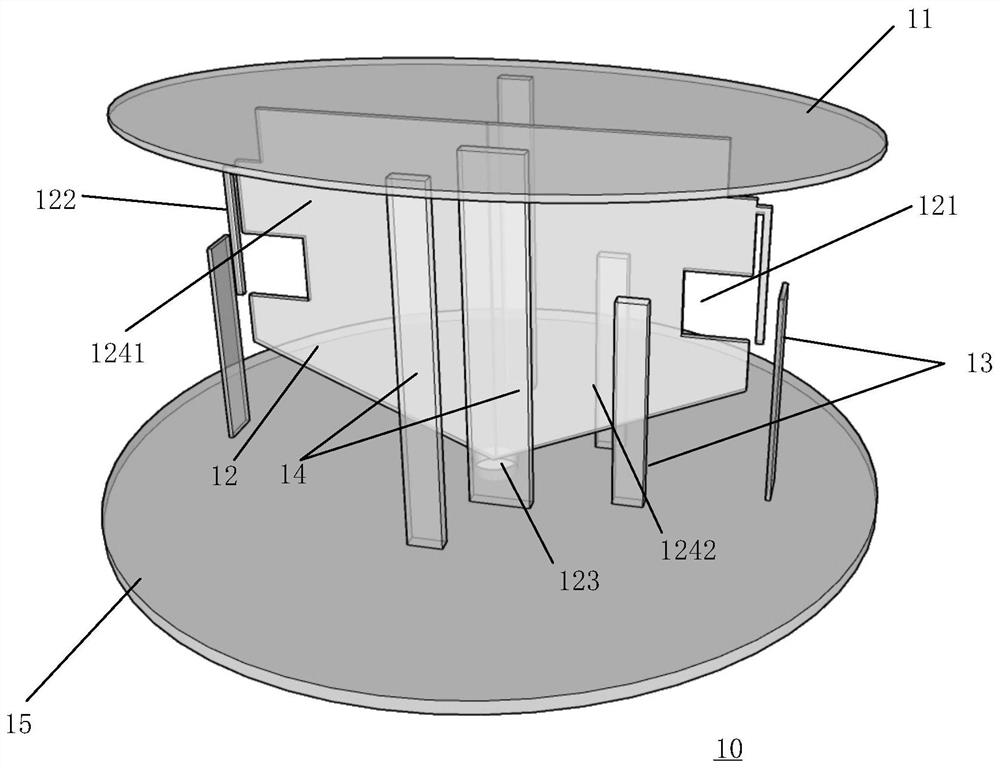
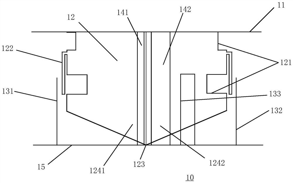
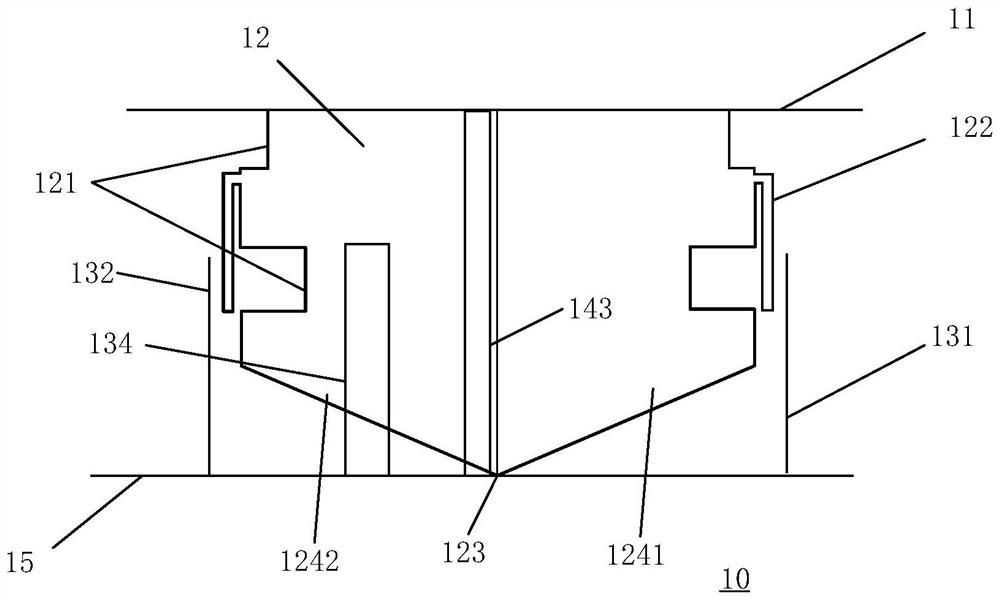
The invention discloses an ultra-wideband antenna, which comprises a top loading plate and a metal floor which are opposite to each other, a radiation part positioned between the top loading plate and the metal floor, and a short circuit column and a parasitic oscillator which are arranged between the metal floor and the top loading plate, the radiation part is of an axial symmetry structure, the symmetry axis penetrates through the center of the top loading plate and the center of the metal floor, the radiation part comprises a first radiation body and a second radiation body which are arranged in an axial symmetry mode and located on the same plane, each radiation body is in a knife shape, the inner side edges of the radiation bodies are connected in a back-to-back mode, and grooves and side loading strips are formed in the outer side edges of the radiation bodies. And the side loading strips are parallel to the symmetry axis and extend towards the direction of the metal floor. According to the invention, the elliptical disc-shaped top loading plate, the grooves in meandering flow design and the side loading strips are adopted, so that the size of the antenna is effectively reduced, the working bandwidth of the antenna is widened, and meanwhile, the side loading strips can be grounded and / or the widths of the side loading strips and the parasitic oscillators are reasonably designed, so that the high-frequency and low-frequency radiation characteristics of the antenna are adjusted, and the gain is improved.

Description

technical field [0001] The invention relates to the technical field of antennas, in particular to an ultra-wideband antenna. Background technique [0002] Very high frequency / ultra high frequency (VHF / UHF) is also called ultrashort wave, and its wireless communication frequency range is 30MHz-512MHz. Ultrashort wave communication has the advantages of wide available frequency, simple manufacture, and small equipment size, which makes ultrashort wave communication widely used in military and civilian fields. Ultrashort wave frequency hopping communication is an important means of communication, especially in modern military communications, in order to achieve confidential communication and eliminate interference, multi-band, multi-functional radios and broadband frequency hopping radios are widely used. Ultrashort wave frequency hopping communication has a strong Data transmission and anti-interference ability, in addition, frequency hopping communication technology also has...

Claims


Application Information

Patent Timeline
Patent Type & Authority Applications(China)
IPC IPC(8): H01Q1/36H01Q1/48H01Q1/50
CPCH01Q1/36H01Q1/48H01Q1/50
Inventor 刘若鹏赵治亚李长江马冰
Owner SHENZHEN KUANG CHI HIGH END EQUIP TECH DEV LTD
Learn More