
Patsnap Eureka
For R&D, Patsnap Eureka makes reading and utilizing patents & technical documents easy.
Patsnap Eureka AIR
Designed for self-driven R&D workflows. Generate viable solutions, solve complex R&D challenges, empower your innovation with AI.

Patsnap Eureka Materials
Designed for material experts only. Revolutionize your material R&D, from search, analyze, to developing new materials.

TechResearch
Generate reliable direction feasibility study reports for your R&D in just a few steps.

TechSeek
Discover and master advanced knowledge NOW. Basics, ideas, possibilities, all at once.

TechMind
As an expert in R&D Theories, TechMind can generates customized viable solutions instantly.

TechRisk
Analyze your overall solution with one click, know your potential R&D risks in advance.

TechMonitor
Get weekly tech updates, stay abreast of the latest tech innovations and key insights.
A fuel cell recovery method
A fuel cell and recovery method technology, which is applied in the direction of fuel cells, circuits, electrical components, etc., can solve the problems of reducing the service life of fuel cells, fuel cell performance attenuation, and proton exchange membrane attenuation, so as to improve user experience and restore output performance , the effect of restoring performance output
- Summary
- Abstract
- Description
- Claims
- Application Information
AI Technical Summary
Problems solved by technology
Method used
Image

Examples
Embodiment 1
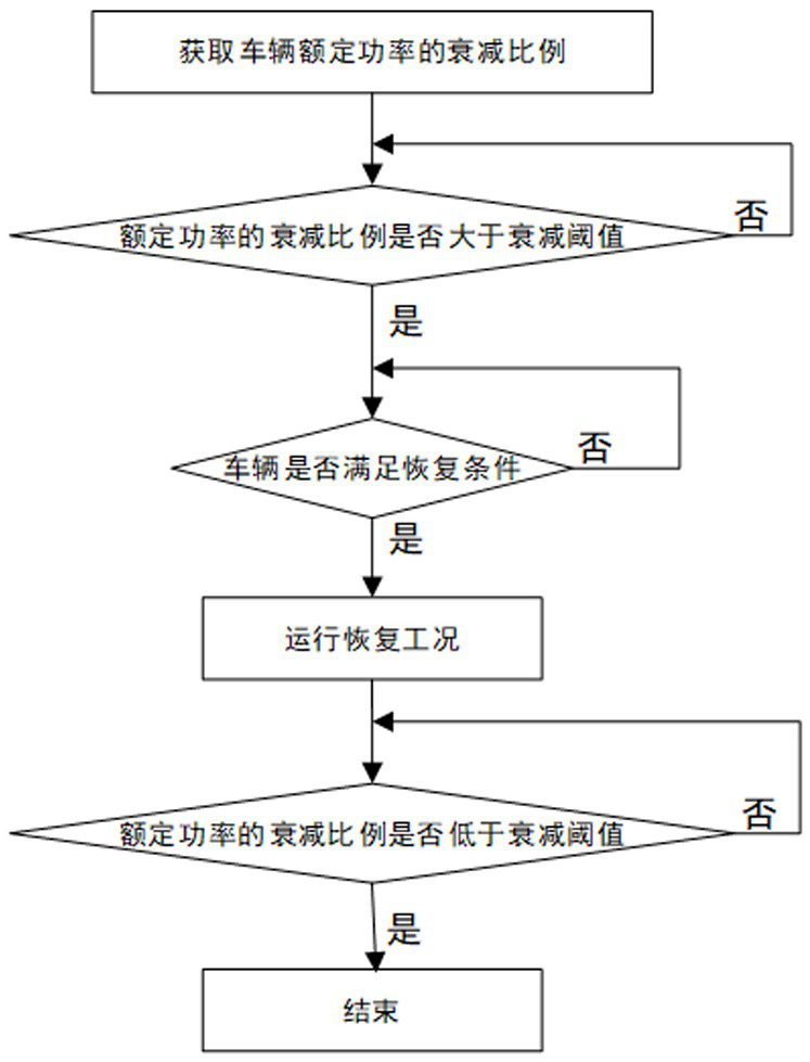
[0028] refer to figure 1 , a fuel cell recovery method of the present invention, comprising the following steps:
[0029] S1. Detect the attenuation ratio of the output rated power of the fuel cell system: calculate the difference between the calibrated output power and the actual output power to obtain the power drop value, and then calculate the ratio of the power drop value to the calibrated output power to obtain the attenuation of the rated power Proportion; determine whether the attenuation ratio of the rated power is greater than the attenuation threshold; if so, enter the next step; if not, the fuel cell does not need to be restored; the attenuation threshold is 2% of the initial power;
[0030] S2. Whether the system self-test meets the recovery conditions; if so, go to the next step; if not, it cannot be recovered;
[0031] S3. Under the rated current gear, gradually reduce the cathode inlet pressure. The step size of the pressure reduction is 2KPa, and the interval...
Embodiment 2
[0034] S1. Detect the attenuation ratio of the output rated power of the fuel cell system; calculate the difference between the calibrated output power and the actual output power to obtain the power drop value, and then calculate the ratio of the power drop value to the calibrated output power to obtain the attenuation of the rated power Proportion; determine whether the attenuation ratio of the rated power is greater than the attenuation threshold; if so, enter the next step; if not, the fuel cell does not need to be restored; the attenuation threshold is 10% of the initial power;
[0035] S2. Whether the system self-test meets the recovery conditions; if so, go to the next step; if not, it cannot be recovered;
[0036] S3. Under the rated current gear, gradually reduce the cathode inlet pressure, the step size of step-down is 6KPa, and the interval is 15 seconds. The anode inlet pressure is kept higher than the cathode pressure by 15KPa, and the average single-chip voltage V...
Embodiment 3
[0039]S1. Detect the attenuation ratio of the output rated power of the fuel cell system: Calculate the difference between the calibrated output power and the actual output power to obtain the power drop value, and then calculate the ratio of the power drop value to the calibrated output power to obtain the attenuation of the rated power Proportion; determine whether the attenuation ratio of the rated power is greater than the attenuation threshold; if so, enter the next step; if not, the fuel cell does not need to be restored; the attenuation threshold is 20% of the initial power;
[0040] S2. Whether the system self-test meets the recovery conditions; if so, go to the next step; if not, it cannot be recovered;
[0041] S3. Under the rated current gear, gradually reduce the cathode inlet pressure. The step size of step-down is 10KPa, and the interval is 30 seconds. The anode inlet pressure is kept higher than the cathode pressure by 30Pa. If it is lower than the minimum rated...
PUM
 Abstract
Description
Claims
Application Information
 - R&D Engineer
- R&D Manager
- IP Professional
- Industry Leading Data Capabilities
- Powerful AI technology
- Patent DNA Extraction
Browse by: Latest US Patents, China's latest patents, Technical Efficacy Thesaurus, Application Domain, Technology Topic, Popular Technical Reports.
© 2024 PatSnap. All rights reserved.Legal|Privacy policy|Modern Slavery Act Transparency Statement|Sitemap|About US| Contact US: help@patsnap.com