
Micro-channel radiator and micro-scale topological optimization design method thereof

A topology optimization and design method technology, applied in design optimization/simulation, computer-aided design, calculation, etc., can solve problems such as initial design dependence, unclear description of structural boundaries, small channel size of microchannel radiators, etc. Achieve the effects of reducing computing time consumption, eliminating subjective dependence, and avoiding human influence

Pending Publication Date: 2021-07-09
HUAZHONG UNIV OF SCI & TECH
View PDF0 Cites 4 Cited by
  • Summary
  • Abstract
  • Description
  • Claims
  • Application Information

AI Technical Summary

Problems solved by technology

The variable density method has better solution stability and simple calculation, but it may generate more intermediate density units, which makes it unclear about the structure boundary
The level set method can clearly describe the structural boundary, but the traditional level set method needs to solve the H-J PDE, and the calculation is more complicated
The parametric level set method can avoid solving the H-J PDE, but it has not been applied to the field of flow channel radiator design; and its research mostly uses regular grids, which is difficult to meet the design requirements of parts with complex geometric shapes, and its porous initial design is artificial. for selection, prone to initial design dependencies
The size of the flow channel of the micro-channel radiator is small, and the overall design at the macro scale requires a large number of mesh units, and at the same time, the method of flow channel size constraint is required, and the calculation cost is relatively large.

Method used


Image

  • Micro-channel radiator and micro-scale topological optimization design method thereof
  • Micro-channel radiator and micro-scale topological optimization design method thereof
  • Micro-channel radiator and micro-scale topological optimization design method thereof

Examples


Embodiment

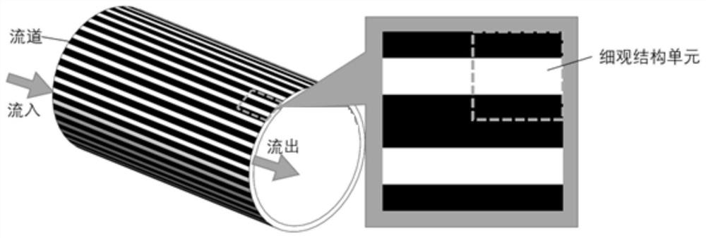
[0103] The embodiment of the present invention provides a method for topological optimization design of micro-scale heat dissipation micro-channels, and in this embodiment, a radiator with a cylindrical wall micro-channel is used as an example to illustrate the method, and the parameters are not dimensioned. The heat sink is cylindrical, the heat source is located in the cavity in the middle of the cylinder, and the heat dissipation flow channel is located inside the tube wall, which belongs to the thin-walled flow channel design, so two-dimensional instead of three-dimensional. The initial design is a parallel flow channel, such as figure 2 As shown in the figure, the black texture on the outer surface is used to represent the flow channel, and the following pictures also use this description method. Assuming that the heat flux density of the tube wall is uniform, the heat production coefficient is taken as β=100, the fluid density is taken as ρ=1, and the dynamic viscosity ...


PUM


Abstract

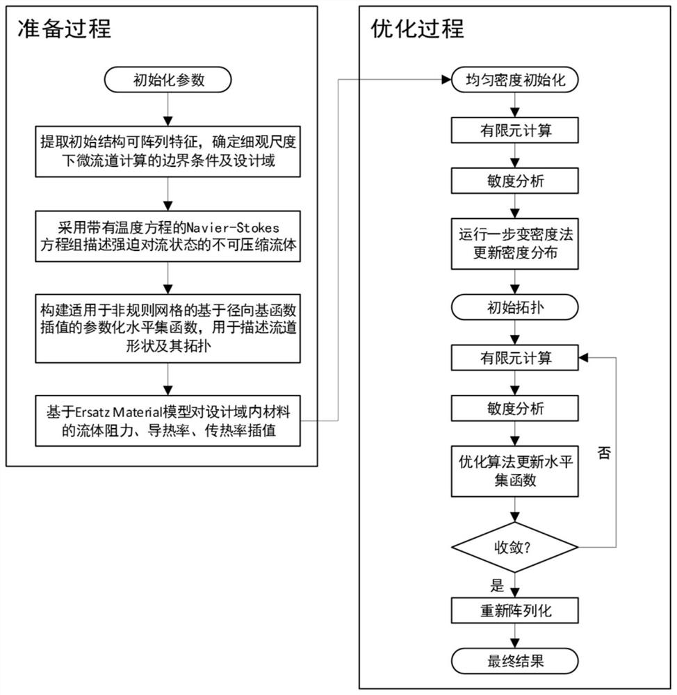
The invention belongs to the related technical field of heat flow coupling topological optimization design, and discloses a micro-channel radiator and a micro-scale topological optimization design method thereof, and the method comprises the following steps: firstly, carrying out the local feature extraction of the micro-channel radiator to obtain a micro-scale unit, taking the micro-scale unit as a design object, and carrying out finite element grid division on the mesoscopic units; and then, based on the finite element grid in the design domain of the micro-scale unit, obtaining a micro-channel topological structure under the micro-scale through a parameterized level set topological optimization method, and arraying the micro-channel topological structure under the micro-scale to obtain the micro-channel radiator. According to the method, the micro-channel radiator is divided into a plurality of micro-scale units, and topological optimization design is carried out by taking the micro-scale units as objects, so that a large number of finite element grid units are prevented from being divided in order to describe small channels during macroscopic design, the calculation overhead is saved, and the calculation efficiency is improved.

Description

technical field [0001] The invention belongs to the related technical field of heat flow coupling topology optimization design, and more specifically relates to a micro-channel radiator and a method for topology optimization design of the micro-scale. Background technique [0002] Liquid cooling radiators are widely used in many engineering fields, such as high-power electronic equipment, engines, heat exchangers, aerospace vehicles, etc. For example, in aerospace, the design of the regenerative cooling channel of the engine belongs to the category of liquid cooling radiator design in essence; The heat dissipation system design puts forward higher requirements. Due to its high specific surface area, the micro-channel radiator can achieve a heat transfer coefficient several times that of the traditional channel radiator, and its small size allows multi-scale and array design. Traditional structural design methods based on experience are difficult to further improve heat dis...

Claims


Application Information

Patent Timeline
Patent Type & Authority Applications(China)
IPC IPC(8): G06F30/23G06F30/28G06F119/08
CPCG06F30/23G06F30/28G06F2119/08
Inventor 高亮李家靖李好
Owner HUAZHONG UNIV OF SCI & TECH
Learn More