Measurement system and method with rolling angle self-correction function

A measurement system and roll angle technology, applied in measurement devices, instruments, optical devices, etc., can solve the problems of complex optical path, difficult to guarantee accuracy, difficult application, etc., and achieve the effect of simple optical path structure, improved measurement accuracy, and easy integration.

Active Publication Date: 2021-07-09
DALIAN UNIV OF TECH
View PDF6 Cites 0 Cited by
  • Summary
  • Abstract
  • Description
  • Claims
  • Application Information

AI Technical Summary

Problems solved by technology

Although there are a large number of roll angle measurement methods, there are still shortcomings such as difficult to guarantee accuracy, difficult to implement applications, complex optical paths, and excessively large volumes that cannot be integrated.
For example, based on the interferometry, Lee C designed a measurement system for the measurement of the six-degree-of-freedom motion error of the ultra-precision guide rail. The angular resolution can reach 0.02″, and the measurement range is relatively short; In the error, Kuang Cuifang et al. proposed a polarization difference measurement method using a 1 / 4 wave plate as a sensitive unit. This method has a simple structure, but has high requirements on the stability of the light source, and its roll angle sensitivity is not high; in the geometric method, K.C.Fan proposed a parallel double-beam method to measure the roll angle indirectly, but this method requires extremely high parallelism between the two beams

Method used


Image

  • Measurement system and method with rolling angle self-correction function
  • Measurement system and method with rolling angle self-correction function
  • Measurement system and method with rolling angle self-correction function

Examples


Embodiment Construction

[0034] In order to facilitate those of ordinary skill in the art to understand and implement the present invention, the present invention will be further described in detail below in conjunction with the accompanying drawings and examples.

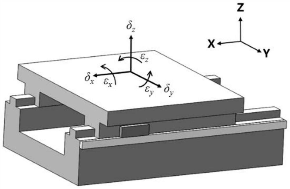
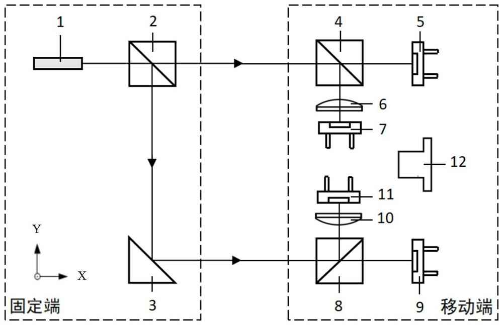
[0035] as attached figure 2As shown, the technical solution adopted in the present invention is: a five-degree-of-freedom error measurement system with the function of monitoring the non-parallelism of the double beams, the measurement system includes a semiconductor laser 1, a first beam splitter 2, a right-angle mirror 3, The second dichroic prism 4, the first four-quadrant photodetector 5, the first focusing lens 6, the second four-quadrant photodetector 7, the third dichroic prism 8, the third four-quadrant photodetector 9, the second focusing lens 10 , the fourth four-quadrant photodetector 11, the laser ranging module 12; wherein, the semiconductor laser 1, the first beam splitting prism 2, and the right-angle reflector 3 are instal...


PUM


Abstract

The invention belongs to the technical field of motion precision measurement of linear workbenches, and discloses a measurement system and method with a rolling angle self-correction function. The mode of measuring the rolling angle through double light beams needs to ensure that the two light beams are parallel in principle to measure accurate rolling angle errors, however, due to the fact that a right-angle reflecting mirror is mounted on a small two-dimensional angle adjusting frame, a spring component in the right-angle reflecting mirror cannot be inevitably changed slightly after a long time, and due to the reasons such as angle drift of the laser, tiny angle change is generated between the two beams of light, so that the measurement accuracy of the rolling angle error is influenced by non-parallelism generated by the two beams of light, and the non-parallelism generated by the two beams of light is shown in the figure 4. The non-parallelism between the two beams of light can be reflected to two calibration instruments for measuring the pitch angle error, so that the change between the non-parallelism of the two beams of light can be monitored in real time through double-calibration instruments, and then the change is compensated to the roll angle, so that the real roll angle error can be obtained.

Description

technical field [0001] The invention belongs to the technical field of motion precision measurement of a linear workbench, in particular to a five-degree-of-freedom error measurement system and method with the function of monitoring the non-parallelism of double beams. Background technique [0002] With the development of modern science and technology, in high-end manufacturing fields such as aerospace, military industry and national defense, medical equipment, etc., due to the extremely high requirements for the processing accuracy of parts and components, the processing accuracy of CNC machine tools that play the role of core productivity has been raised. higher and higher requirements. The accuracy of the linear workbench on the machine tool directly affects the machining accuracy of the CNC machine tool, so the error measurement of the linear workbench is a key step to improve the machining accuracy of the machine tool. [0003] When the linear table of the machine tool...

Claims


Application Information

Patent Timeline
IPC IPC(8): G01B11/26G01B11/27
CPCG01B11/26G01B11/272
Inventor 娄志峰宋治崑张忠宁
Owner DALIAN UNIV OF TECH
Why Eureka
Try Eureka