
Water ring vacuum system with coil pipe condensation cylinder

A vacuum system, a technology of a water ring vacuum pump, which is applied to parts of pumping devices for elastic fluids, liquid fuel engines, rotary piston type/swing piston type pump parts, etc., and can solve the problem of low working efficiency of water ring vacuum pumps, etc. problem, achieve the effect of improving the cooling efficiency and ensuring the suction effect

Pending Publication Date: 2021-07-09
XIAN THERMAL POWER RES INST CO LTD +1
View PDF18 Cites 2 Cited by
  • Summary
  • Abstract
  • Description
  • Claims
  • Application Information

AI Technical Summary

Problems solved by technology

[0004] The purpose of the present invention is to overcome the shortcomings of the above-mentioned prior art and provide a water ring vacuum system with a coiled tube condensation cylinder to solve the technical problem of low working efficiency of the water ring vacuum pump in the prior art

Method used


Image

  • Water ring vacuum system with coil pipe condensation cylinder
  • Water ring vacuum system with coil pipe condensation cylinder
  • Water ring vacuum system with coil pipe condensation cylinder

Examples


Embodiment Construction

[0027] The present invention is described in further detail below in conjunction with accompanying drawing:

[0028] In the description of the present invention, it should be noted that the terms "center", "upper", "lower", "left", "right", "vertical", "horizontal", "inner", "outer" etc. The indicated orientation or positional relationship is based on the orientation or positional relationship shown in the drawings, and is only for the convenience of describing the present invention and simplifying the description, rather than indicating or implying that the referred device or element must have a specific orientation, or in a specific orientation. construction and operation, and therefore cannot be construed as limiting the present invention; the terms "first", "second", and "third" are used for descriptive purposes only, and cannot be construed as indicating or implying relative importance; in addition, unless otherwise Clearly stipulated and limited, the terms "installation"...


PUM


Abstract

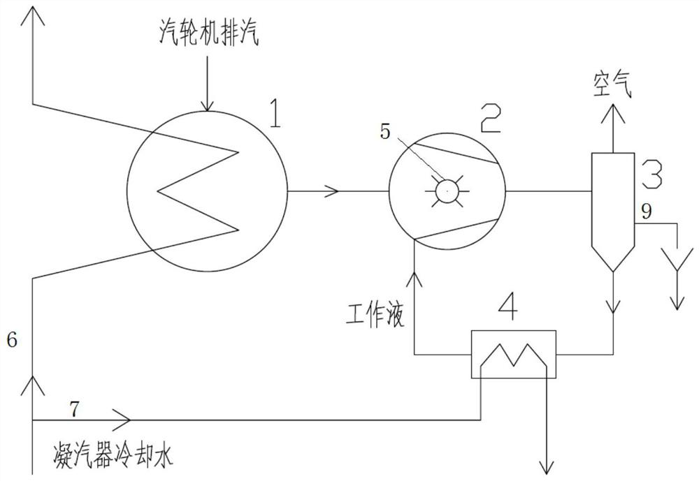
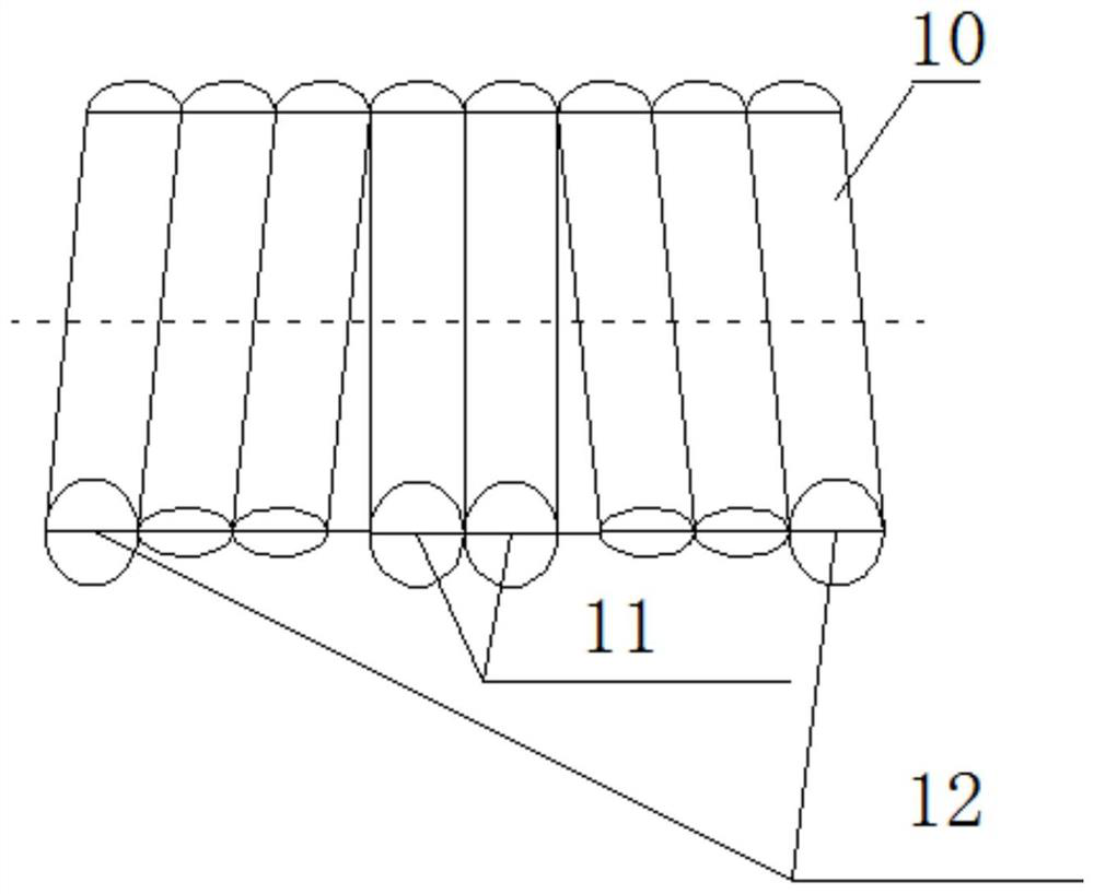
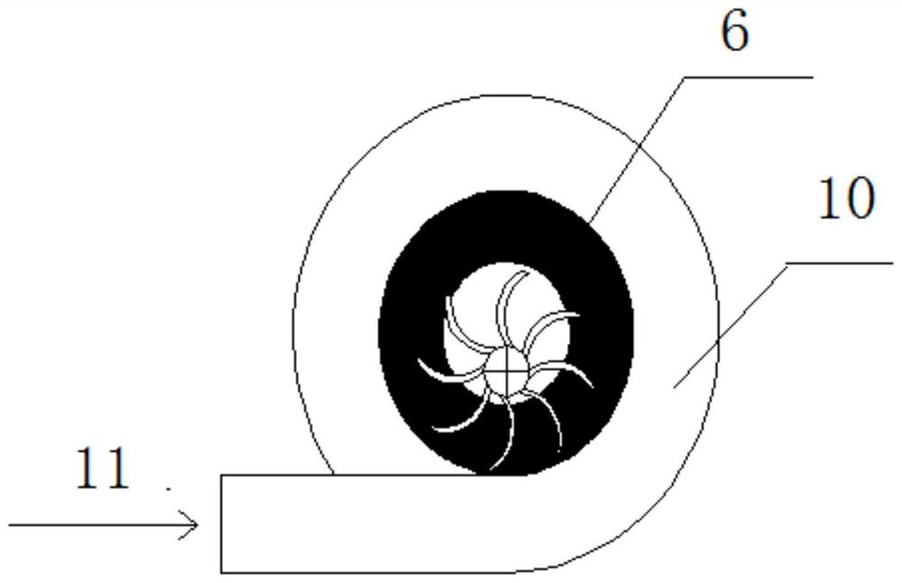
The invention discloses a water ring vacuum system with a coil pipe condensation cylinder. The water ring vacuum system is characterized in that a water ring vacuum pump cylinder is designed into a coil pipe structure for condensate water to pass through; and through transformation on an equipment body, the suction effect of a water ring vacuum pump is ensured to the greatest extent, and isothermal compression in the water ring vacuum pump is realized as far as possible. In the operation process of the water ring vacuum pump, the condensate water is introduced into the coil pipe cylinder and performs non-contact heat exchange with a water ring formed by the working fluid in the cylinder, so that the working fluid of the water ring vacuum pump is further cooled, and the cooling efficiency of the water ring vacuum pump is improved.

Description

technical field [0001] The invention belongs to the field of energy saving and consumption reduction of thermal power units, and in particular relates to a water ring vacuum system with a coil condensing cylinder. 【Background technique】 [0002] The exhaust steam of the steam turbine in the vacuum system of the thermal power unit is cooled by the condenser, and the non-condensable gas is sucked by the water ring vacuum pump and then discharged through the steam-water separator. Among them, the role of the water ring vacuum pump is very important, it will discharge the non-condensable gas from the negative pressure equipment to the atmosphere. [0003] The suction effect of the water ring vacuum pump is related to the temperature of the working fluid. As the temperature of the working fluid increases, the suction rate of the water ring vacuum pump decreases; when the temperature of the working fluid rises to the saturation temperature corresponding to the pressure of the suct...

Claims


Application Information

Patent Timeline
Patent Type & Authority Applications(China)
IPC IPC(8): F04C19/00F04C25/02F04C29/04
CPCF04C19/00F04C19/004F04C25/02F04C29/04
Inventor 邹洋李高潮荆涛王明勇万超韩立贾明晓李永康陈恺任丽君王斌
Owner XIAN THERMAL POWER RES INST CO LTD
Learn More