
Composite bending-moment-free support beam for wireless force measurement

A combined, supporting beam technology, applied in the direction of measuring force, elastic deformation force measurement through measuring gauges, measuring devices, etc., can solve the problem of not being able to observe the stress and strain of the beam body under force and deformation, and unable to judge the supporting beam Problems such as deformation and fatigue stress, failure to meet the hoisting requirements of equipment with different diameters, etc., achieve high assembly efficiency, low use cost, and avoid the effects of horizontal tension

Pending Publication Date: 2021-07-09
CHINA NUCLEAR IND MECHANICAL ENG
View PDF0 Cites 0 Cited by
  • Summary
  • Abstract
  • Description
  • Claims
  • Application Information

AI Technical Summary

Problems solved by technology

[0002] At present, in the field of hoisting technology in various basic construction industries such as nuclear power, petrochemical, electric power, municipal, transportation, etc., hoisting support beams are frequently used. The existing support beams are all integrated support beams. The outside has no bending moment, but its size is fixed, it is not adjustable, and it cannot meet the hoisting requirements of equipment with different diameters, and most of the supporting beams used for hoisting are used for high-altitude operations, and the stress and strain of the beam body and the impact of the beam body cannot be observed with the naked eye. Therefore, it is impossible to judge the deformation and fatigue stress of the support beam, and the absolute safety of the support beam cannot be guaranteed.

Method used


Image

  • Composite bending-moment-free support beam for wireless force measurement
  • Composite bending-moment-free support beam for wireless force measurement
  • Composite bending-moment-free support beam for wireless force measurement

Examples


Embodiment

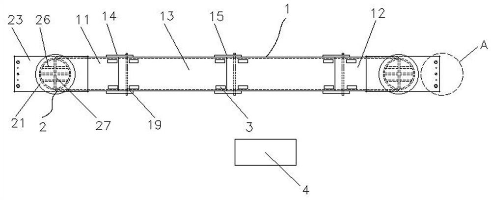
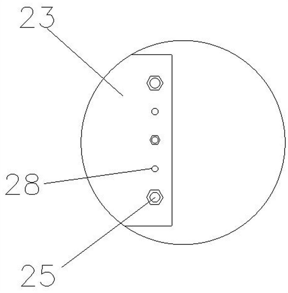
[0026] Embodiment: a wireless force measurement combined non-bending moment support beam (see attached Figure 1-5), including the main beam 1 and the stress indicator 4, the two ends of the main beam are equipped with a rope mechanism 2, the rope mechanism 2 is fixedly connected with the main beam 1, and the main beam 1 includes a first end beam 11 and a second end beam 12 And the composite beam 13, the composite beam 13 is arranged in the middle of the first end beam 11 and the second end beam 12, the first end beam 11 and the second end beam 12 are detachably connected with the composite beam 13, the second One end beam 11 is provided with a hanging rope mechanism 2, the other end of the first end beam 11 is provided with a fixed plate 14, one end of the fixed plate 14 is fixedly linked with the first end beam 11, and the other end of the fixed plate 14 is provided with five connecting holes 16 One end of the composite beam 13 is provided with an assembly hole 19 correspond...


PUM


Abstract

The invention discloses a composite bending-moment-free support beam for wireless force measurement. The composite bending-moment-free support beam comprises a main beam and a stress indicator, wherein rope hanging mechanisms are arranged at two ends of the main beam, and the rope hanging mechanisms are fixedly connected with the main beam; the main beam comprises a first end beam, a second end beam and composite beams; the composite beams are arranged between the first end beam and the second end beam; and the first end beam and the second end beam are detachably connected with the corresponding composite beams. According to the composite bending-moment-free support beam for wireless force measurement, the usage amount of high-strength bolts is reduced, the assembly time is greatly shortened, the assembly efficiency is high, and the use cost is low, so that the time of high-altitude operation is greatly shortened, and the danger coefficient of the high-altitude operation is reduced; and the stress-strain condition of the whole main beam can be monitored, and the support deformation condition and the fatigue stress condition can be quickly and effectively judged, so that the relative safety of the support beam is ensured.

Description

technical field [0001] The invention relates to the field of mechanical equipment, and more specifically, the invention relates to a wireless force-measuring combined non-bending moment support beam. Background technique [0002] At present, in the field of hoisting technology in various basic construction industries such as nuclear power, petrochemical, electric power, municipal, transportation, etc., hoisting support beams are frequently used. The existing support beams are all integrated support beams. The outside has no bending moment, but its size is fixed, it is not adjustable, and it cannot meet the hoisting requirements of equipment with different diameters, and most of the supporting beams used for hoisting are used for high-altitude operations, and the stress and strain of the beam body and the impact of the beam body cannot be observed with the naked eye. Therefore, it is impossible to judge the deformation and fatigue stress of the support beam, and the absolute ...

Claims


Application Information

Patent Timeline
Patent Type & Authority Applications(China)
IPC IPC(8): B66C1/12B66C13/04B66C15/00G01L1/04
CPCB66C1/12B66C13/04B66C15/00G01L1/04B66C13/16G01L1/2212G01L1/225
Inventor 邝小娟贾金廷彭燕荣
Owner CHINA NUCLEAR IND MECHANICAL ENG
Learn More