Method for eliminating view blind area of A pillar of vehicle body by using lightweight mirror group and mirror group

A lightweight, mirror group technology, applied in vehicle parts, optical observation devices, transportation and packaging, etc., can solve the problems of airbag popping, hidden dangers, etc., and achieve the effect of increasing safety, reducing inertial force, and avoiding fragmentation.

Pending Publication Date: 2021-07-09
丁起武
View PDF0 Cites 0 Cited by
  • Summary
  • Abstract
  • Description
  • Claims
  • Application Information

AI Technical Summary

Problems solved by technology

[0004] The object of the present invention is to provide a method and a mirror group for eliminating the blind spot of the A-pillar of the car body by using a lightweight mirror group, aiming at solving the problem of installing reflectors or built-in cameras in the A-pillar, B-pillar, and C-pillar areas of the car. Solve the problem of potential safety hazards when the airbag pops up in the blind area of ​​the column area

Method used


Image

  • Method for eliminating view blind area of A pillar of vehicle body by using lightweight mirror group and mirror group
  • Method for eliminating view blind area of A pillar of vehicle body by using lightweight mirror group and mirror group
  • Method for eliminating view blind area of A pillar of vehicle body by using lightweight mirror group and mirror group

Examples


Embodiment 1

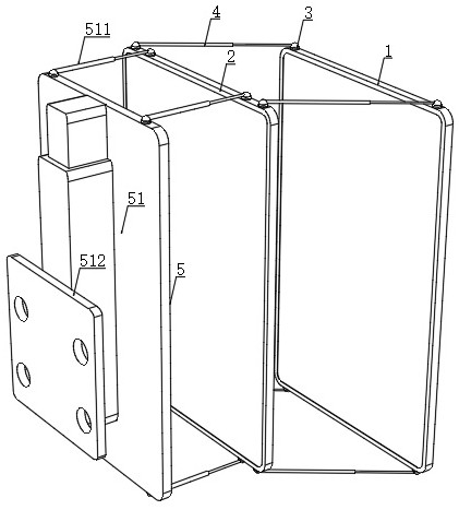
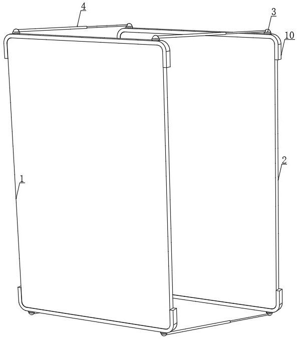
[0031] see Figure 1-5 , the present invention provides the following technical solutions: a method for eliminating the blind area of ​​the A-pillar field of view of the car body by using a lightweight mirror group, comprising the following steps:

[0032] S1, material selection, the mirror solid layer of the mirror group is made of non-metal (non-traditional silicate glass), with high toughness, high strength and lightweight polymer organic material as the main material, of course, it can also be used with anti-crack Glass or a mirror with a thin metal layer as the mirror material;

[0033] S2, mirror group selection, in a small car or off-road vehicle with an airbag on the A-pillar, the total mass of the mirror group is less than 400g, because the first reflector 1 is farther away from the A-pillar, the A-pillar decorative plate has less protective effect on it, The instantaneous inflation of the A-pillar airbag has a greater impact on the first reflector. It is safer to ha...

Embodiment 2

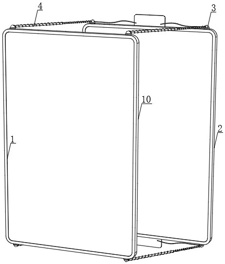
[0050] see Image 6 , the difference technical feature of this embodiment compared with embodiment 1 is: the mirror group adopts two groups, by installing two groups of mirror groups on both sides of the A-pillar to form a composite mirror group, through the composite mirror group Imaging of blind spots can also be realized.

[0051] It should also be added that this method of using mirrors to form images to eliminate blind spots can also be applied to vehicles such as buses, engineering vehicles, trains, ships, and aircrafts. The mirror surface is not limited to flat mirrors, and curved surfaces can also be selected according to needs. For convex mirrors and concave mirrors with a radius greater than 15cm, the second reflector can also be equipped with suction cups, magnetic stickers and Velcro stickers on the back. on the windshield.


PUM


Abstract

The invention provides a method for eliminating a view blind area of A pillar of a vehicle body by using a lightweight mirror group and the mirror group. The method comprises the following steps: S1, selecting materials; S2, selecting a lens group; S3, installing the lens group; and S4, performing mirror group imaging, wherein only even-order reflection images such as 2.4.6.8... (n-2) n are formed when the reflection image on a second reflecting mirror is matched with the image reflected by a first reflecting mirror. According to the invention, a pair of light-weight reflecting mirror groups in which two mirror surfaces are opposite to each other, a certain distance is kept, the two mirror surfaces are approximately parallel, and the two mirror surfaces are staggered in a translation manner is adopted to effectively reduce the visual width of the A pillar; and the two mirror surfaces are translates and staggered, in the view angle of an observer, a reflection image of a distant scenery on the second reflecting mirror can be observed by completely not shielding or only partially shielding the other plane mirror (the second reflecting mirror) by the near plane mirror (the first reflecting mirror), the reflection image of an object behind the second reflecting mirror is only even-order reflection images such as 2.4.6.8... and the like, the even-order reflection images are all positive images, and the object is visually imaged.

Description

technical field [0001] The invention belongs to the technical field of vehicle safety, and in particular relates to a method and a mirror group for eliminating blind spots of an A-pillar of a vehicle body by using a lightweight mirror group. Background technique [0002] The distance between the center points of the double pupils of an adult is about 6.0 cm. For an obstruction with a width greater than 6.0 cm, on the horizontal plane of the double pupils, the straight line passing through the center point of the left pupil and the left edge of the obstruction and the center point of the right pupil The straight line with the right edge of the occluder will inevitably intersect at a place where the occluder is farther than the pupils, forming a binocular overlap angle. In the direction where the occluder is far away from the pupils, a visual blind zone enlarged at this angle will inevitably be formed. [0003] At present, the binocular overlap angle of the A-pillar of various...

Claims


Application Information

Patent Timeline
Patent Type & Authority Applications(China)
IPC IPC(8): B60R1/00
CPCB60R1/00B60R2300/8006
Inventor 丁起武
Owner 丁起武
Why Eureka
Try Eureka