
Novel synchronous reluctance motor rotor structure

A synchronous reluctance motor, rotor structure technology, applied in the magnetic circuit shape/style/structure, magnetic circuit rotating parts, magnetic circuit and other directions, can solve the problem of large torque ripple, low salient pole ratio, synchronous reluctance motor Serious problems such as rotor leakage inductance

Inactive Publication Date: 2021-07-06
HARBIN UNIV OF SCI & TECH
View PDF5 Cites 1 Cited by
  • Summary
  • Abstract
  • Description
  • Claims
  • Application Information

AI Technical Summary

Problems solved by technology

[0004] The purpose of the present invention is to provide a rotor structure scheme that solves the problems of serious leakage inductance, low mechanical strength, low salient pole ratio, large torque ripple, and low torque of the synchronous reluctance motor rotor.

Method used


Image

  • Novel synchronous reluctance motor rotor structure
  • Novel synchronous reluctance motor rotor structure

Examples


Embodiment Construction

[0018] The technical solutions in the present invention will be clearly and completely described below in conjunction with the accompanying drawings of the present invention. All other embodiments obtained by persons of ordinary skill in the art based on the present invention without making creative efforts belong to the protection scope of the present invention.

[0019] The purpose of the present invention is to provide a synchronous reluctance motor rotor structure with low leakage inductance, high mechanical strength, high salient pole ratio, high torque and low torque ripple.

[0020] In order to make the above-mentioned purposes, features and advantages of the present invention more obvious and understandable, the present invention will be described in further detail below in conjunction with the accompanying drawings and specific embodiments:

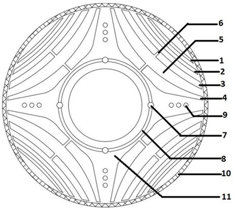
[0021] Such as figure 1 As stated, the present invention is a novel synchronous reluctance motor rotor structure;

[0022] Th...


PUM


Abstract

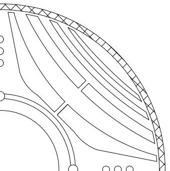
The invention discloses a synchronous reluctance motor rotor structure, which comprises an iron core and an iron core sheath, and is characterized in that the iron core is sequentially provided with a first layer of air magnetic barrier, a second layer of air magnetic barrier, a third layer of air magnetic barrier and a fourth layer of air magnetic barrier from outside to inside, and the first layer of air magnetic barrier, the second layer of air magnetic barrier, the third layer of air magnetic barrier and the fourth layer of air magnetic barrier have different thicknesses; magnetic conductive ribs are arranged between the adjacent air magnetic barriers and on the outer side of the first layer of air magnetic barrier; central ribs with the same thickness are arranged at the middle parts of the third-layer air magnetic barrier and the fourth-layer air magnetic barrier; the iron core is provided with a ventilation hole; and a layer of carbon fiber iron core sheath is wrapped outside the iron core. The synchronous reluctance motor rotor structure can well solve the problems that a motor rotor is serious in leakage inductance, low in mechanical strength, low in salient pole ratio, large in torque pulsation, low in torque and the like.

Description

technical field [0001] The invention relates to the technical field of motors, in particular to a novel synchronous reluctance motor rotor structure. Background technique [0002] With the development of power electronics technology, permanent magnet synchronous motors have been widely used in places with high motor control requirements, but permanent magnet synchronous motors have shortcomings such as too strict temperature restrictions, poor overload capacity, and difficulty in field-weakening speed regulation. At the same time, due to the rapid consumption of rare earth resources in recent years, it is very likely to face a shortage of rare earth resources in the future, hindering the development of permanent magnet synchronous motors. However, synchronous reluctance motor has no permanent magnet on the rotor, simple processing, lower cost, and no problem of high temperature loss of magnetism. These advantages make synchronous reluctance motor have unique advantages in so...

Claims


Application Information

Patent Timeline
Patent Type & Authority Applications(China)
IPC IPC(8): H02K1/24H02K1/32
CPCH02K1/246H02K1/325H02K2213/03
Inventor 戈宝军张凯韩继超
Owner HARBIN UNIV OF SCI & TECH
Learn More