Spatial photometry system calibration device and method based on beam line characteristics
A calibration device and spatial light technology, applied in the field of visual measurement and image detection, can solve the problems of difficulty in target manufacturing and setting, difficult maintenance efficiency, uneven layout, etc., to achieve easy operation and maintenance, improve efficiency, and reduce labor intensity Effect
- Summary
- Abstract
- Description
- Claims
- Application Information
AI Technical Summary
Problems solved by technology
Method used
Image

Examples
Embodiment 1
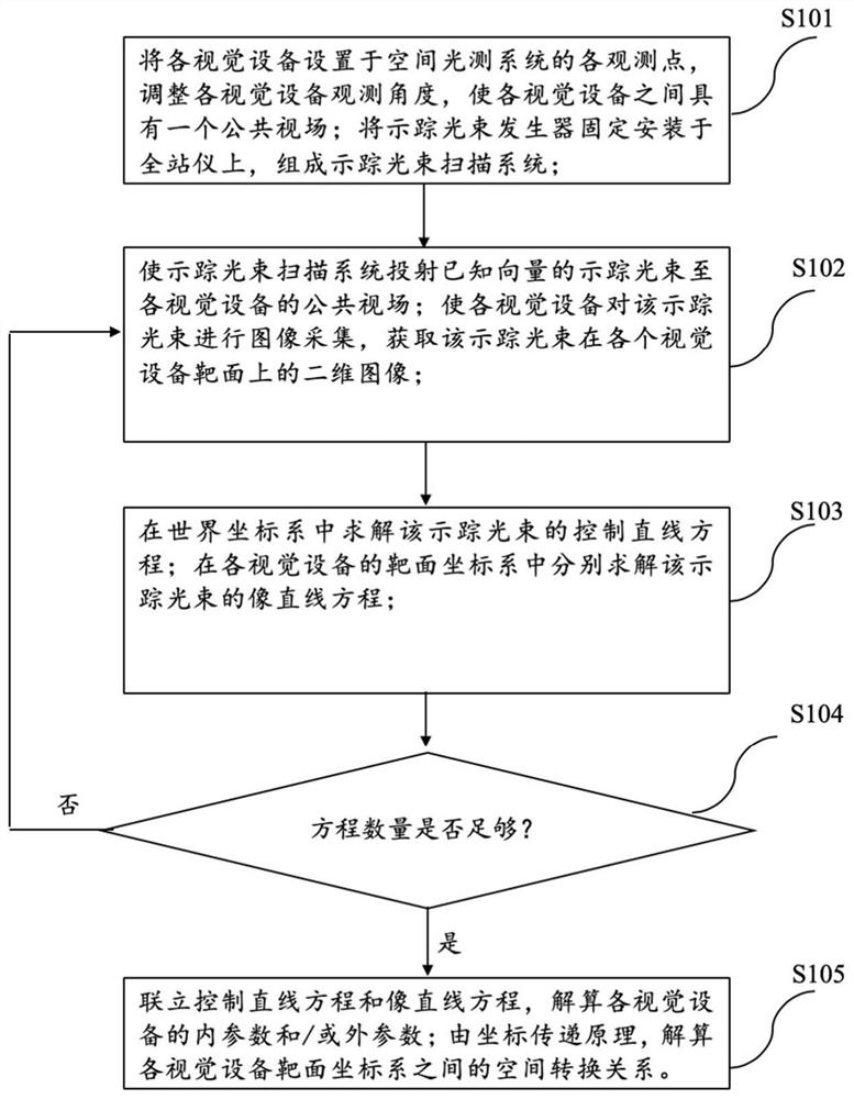
[0040] figure 1 A flow chart of a method for calibrating a spatial photometric system provided by an embodiment of the present invention is shown. In step S101, the left camera and the right camera are set at two observation points corresponding to the spatial photometric system, and the observation angle of each camera is adjusted so that There is a common field of view between each camera; the left camera target surface coordinate system and the right camera target surface coordinate system are established; the tracking beam generator is fixedly installed on the total station to form a tracking beam scanning system;
[0041] In step S102, the tracer beam scanning system is made to project the tracer beam of a known vector to the public field of view of the camera; make each camera carry out image acquisition to this tracer beam, and obtain the two-dimensional image of this tracer beam at each camera;
[0042] In step S103, solve the control line equation of this tracer beam ...
Embodiment 2
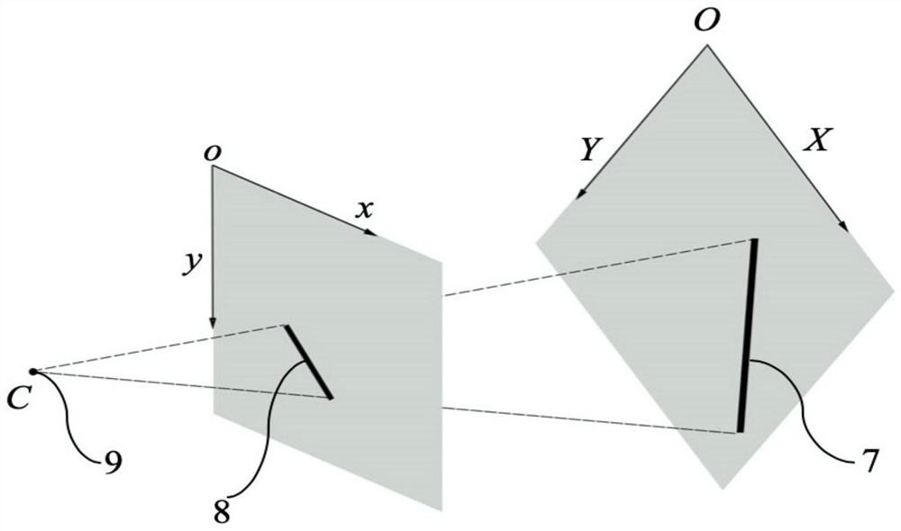
[0082] In this embodiment, a one-dimensional high-precision turntable is selected as the multi-degree-of-freedom turntable, that is, the tracer beam projected by the one-dimensional turntable must be on a plane. For the convenience of calculation, a coordinate system such as figure 2 As shown, a two-dimensional world coordinate system XOY is established on the coplanar plane of each tracer beam, and the control line 7 of the i-th tracer beam is selected, which is the image line 8 of the left camera target surface coordinate system xoy. Without loss of generality, neither the control line 7 nor the image line 8 is parallel to the coordinate axis of the coordinate system where they are located.
[0083] From the high-precision azimuth positioning characteristics of the one-dimensional turntable, the control line equation can be obtained:
[0084] Y=AX+B
[0085] and the corresponding equation like a straight line:
[0086]
[0087] Substitute into the collinear equation
...
Embodiment 3
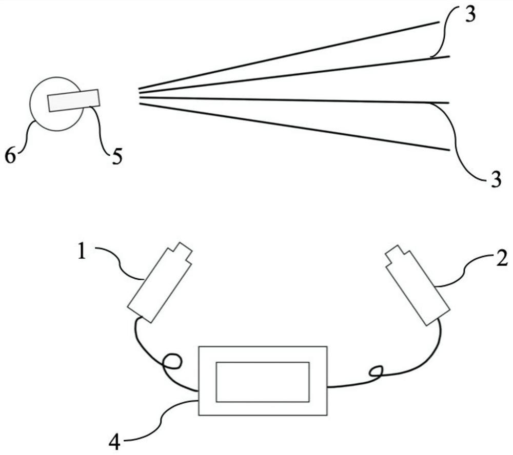
[0109] like image 3 As shown, the embodiment of the present invention also provides a calibration device of a space photometric system, the device comprising:
[0110] The multi-eye vision device group includes two vision devices, the left camera 1 and the right camera 2, which are used for image acquisition of the tracer beam 3 according to the preset projection rules, and output the tracer beam 3 formed on the target surface of each camera. Each camera of the two-dimensional image is arranged at each observation point of the spatial photometric system, and each camera is arranged at a certain angle to each other, and has a common field of view;
[0111] A tracer beam scanning system, used for projecting tracer beams 3 of different orientations to the public field of view of each camera according to a preset projection rule, and outputting the spatial orientation data of each tracer beam;
[0112] The processing system 4 is used to preset projection rules, input the spatial...
PUM
 Abstract
Description
Claims
Application Information
 - R&D
- Intellectual Property
- Life Sciences
- Materials
- Tech Scout
- Unparalleled Data Quality
- Higher Quality Content
- 60% Fewer Hallucinations
Browse by: Latest US Patents, China's latest patents, Technical Efficacy Thesaurus, Application Domain, Technology Topic, Popular Technical Reports.
© 2025 PatSnap. All rights reserved.Legal|Privacy policy|Modern Slavery Act Transparency Statement|Sitemap|About US| Contact US: help@patsnap.com