Eureka AIR delivers breakthrough ideas for toughest innovation challenges, trusted by R&D personnel around the world.

Osteophyte recognition method and device, electronic equipment and storage medium

An identification method and osteophyte technology, applied in the field of image processing, can solve problems such as affecting knee joint function, time-consuming and labor-intensive doctors, and errors.

Active Publication Date: 2021-07-06
LONGWOOD VALLEY MEDICAL TECH CO LTD +2
View PDF6 Cites 7 Cited by
  • Summary
  • Abstract
  • Description
  • Claims
  • Application Information

AI Technical Summary

Problems solved by technology

[0002] In preoperative planning, osteophytes have a great influence on the positioning of key landmarks such as the mechanical axis, joint line, femoral anteroposterior axis, and AP axis. Misjudging the shape and position of osteophytes will lead to deviations in positioning landmarks, thereby affecting the knee joint. Function, stability, range of motion and prone to postoperative pain
Before clinical total knee arthroplasty, doctors need to plan and make decisions based on bone imaging data of the lower limbs without osteophytes. Doctors are better at medical knowledge, and image processing is time-consuming and labor-intensive for doctors.
Experienced doctors can put forward requirements to guide and assist other technicians to perfectly eliminate the osteophytes of lower limb bone images, but they suffer from image processing to eliminate the osteophytes of lower limb bone images by themselves, and inexperienced doctors cannot rely on medical Guided by experience, the osteophyte part of the bone image of the lower limbs can be perfectly eliminated, and it is more difficult to operate by yourself

Method used


Image

  • Osteophyte recognition method and device, electronic equipment and storage medium
  • Osteophyte recognition method and device, electronic equipment and storage medium
  • Osteophyte recognition method and device, electronic equipment and storage medium

Examples


Embodiment 1

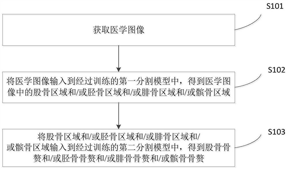
[0038] Embodiment 1 of the present invention provides a bone recognition method. figure 1 A flow schematic of the method of the second embodiment of the present invention. Such as figure 1 As shown, the bone recognition method of the first embodiment of the present invention includes the following steps:

[0039] S101: Get a medical image.

[0040] As a specific embodiment, the medical image is a medical image of a lower extremity bone, such as a lower extremity bone image.

[0041] S102: Enter the medical image into the training-trained first split model to obtain a femoral region and / or tibial region and / or a tibial region and / or a tibia region in the medical image.

[0042] In the first embodiment of the present invention, the first segmentation model is a UNET neural network model comprising a PointRend algorithm, so that high quality high-pixel image segmentation can be achieved. figure 2 Schematic diagram of processing flow for medical images in the first segmentation ...

Embodiment 2

[0070] In accordance with Embodiment 1 of the present invention, Embodiment 2 of the present invention provides a bone recognition device. Figure 4 A structural diagram of the bone recognition apparatus for the second embodiment of the present invention. Such as Figure 4 As shown, the bone recognition apparatus of the second embodiment of the present invention includes a acquisition module 20, a first processing module 22, and a second processing module 24.

[0071] The acquisition module 20 is configured to obtain a medical image.

[0072] The first processing module 22 is configured to input the medical image into the training-trained first segmentation model to obtain the femoral region and / or tibial region and / or the tibia region and / or tibia region in the medical image. ;

[0073] The second processing module 24 is configured to input the femur region and / or the tibial region and / or the tibia region and / or the tibia region to the training-trained second-divided mo...

Embodiment 3

[0076] Embodiments of the present invention also provide an electronic device, which may include processors and memory, wherein the processor and memory can be connected via a bus or otherwise.

[0077] The processor can be a central processor (Central Processing Unit, CPU). The processor can also be other general purpose processors, digital signals, DTLICEAL PROCESSOR, DSPs, specific integrated circuits (ASICs), field programmable gate arrays, FPGAs or others. Programmable logic devices, discrete doors or transistor logic devices, discrete hardware components, oriented, or a combination of various chips described above.

[0078] The memory is a non-transitory computer readable storage medium, and can be used to store a non-transient software program, a non-transitory computer executable program, and a module, such as program commands corresponding to the vehicle display device in the embodiment of the present invention. Module (for example, Figure 4 The acquisition module 20, the...


PUM


Abstract

The invention discloses an osteophyte recognition method and device, electronic equipment and a storage medium. The osteophyte recognition method comprises the following steps: acquiring a medical image; inputting the medical image into a trained first segmentation model to obtain a femur region and / or a tibia region and / or a fibula region and / or a patella region in the medical image; and inputting the femur region and / or the tibia region and / or the fibula region and / or the patella region into a trained second segmentation model to obtain a femur osteophyte and / or a tibia osteophyte and / or a fibula osteophyte and / or a patella osteophyte. Accordingly, the osteophyte can be quickly, accurately and intelligently identified by utilizing the first segmentation model and the second segmentation model. Doctors can be assisted in surgical planning, operation is easy, accuracy is high, and individual differences of patients can be met, and meanwhile, the accuracy of follow-up surgeries can be improved and a large amount of time can be saved for orthopedists by perfecting basis data of preoperative planning and guiding surgical planning and prosthesis selection.

Description

Technical field [0001] The present invention relates to the field of image processing, and more particularly to a bone recognition method, apparatus, electronic device, and storage medium. Background technique [0002] In the preoperative planning, the position of the key to mechanical shaft, joint line, the front and rear axles, the AP axis, the AP axis, the wrong judgment, the position can cause the positioning mark deviation, which affects the knee joint Function, stability, motion range and is easy to cause postoperative pain. Before the clinical full knee joint replacement, the doctor needs to plan and decisive the planning and decision of surgery according to the lower extremity bone video materials that do not contain osteopathions, the doctor is more good at medical knowledge, and image processing can be consumed to be consumed for doctors. Experienced doctors can make demand guidance to assist other technicians to perfectly eliminate the bones of the lower extremity bone...

Claims


Application Information

Patent Timeline
IPC IPC(8): G06K9/62G06K9/34G06N3/04G06N3/08
CPCG06N3/08G06V10/267G06V2201/033G06N3/047G06N3/048G06N3/045G06F18/2431G06F18/2415
Inventor 张逸凌刘星宇
Owner LONGWOOD VALLEY MEDICAL TECH CO LTD
Why Eureka
Eureka Blog
Learn More