
Material hardness detection equipment for high-end equipment manufacturing

A technology of testing equipment and equipment, applied in the direction of testing material hardness, analyzing materials, measuring devices, etc., can solve problems such as cumbersome artificial load

Pending Publication Date: 2021-07-06
罗水成
View PDF2 Cites 3 Cited by
  • Summary
  • Abstract
  • Description
  • Claims
  • Application Information

AI Technical Summary

Problems solved by technology

[0004] In order to overcome the shortcomings of directly using heavy objects to knock the material to detect the hardness, it is necessary to continuously lift and put down the heavy objects manually, which is relatively cumbersome and imposes an excessive load on the manual. The technical problem is: to provide a convenient , material hardness testing equipment for high-end equipment manufacturing that can quickly test the hardness of materials

Method used


Image

  • Material hardness detection equipment for high-end equipment manufacturing
  • Material hardness detection equipment for high-end equipment manufacturing
  • Material hardness detection equipment for high-end equipment manufacturing

Examples


Embodiment 1

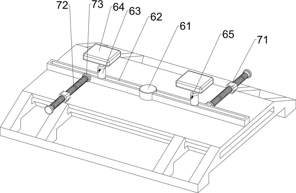
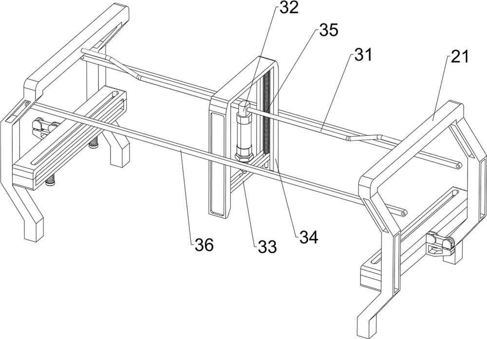
[0054] A material hardness testing equipment for high-end equipment manufacturing, such as figure 1 As shown, it includes a base 1 , a clamping mechanism 2 and a detection mechanism 3 , the top of the base 1 is provided with a clamping mechanism 2 , and the clamping mechanism 2 is provided with a detection mechanism 3 .

[0055] Such as figure 2 As shown, the clamping mechanism 2 includes a mounting frame 21, a first clamping plate 22, a connecting block 23, a first hinge assembly 24, a second clamping plate 25 and a shock absorbing assembly 26, and the left and right sides of the top of the base 1 are provided with mounting brackets. Frame 21, the middle part of the inner side of mounting frame 21 is provided with first clamping plate 22, and the outer side of first clamping plate 22 is provided with connecting block 23, and connecting block 23 is equipped with first hinge assembly 24, and the inside of first hinge assembly 24 is all provided with. A second clamping plate 2...

Embodiment 2

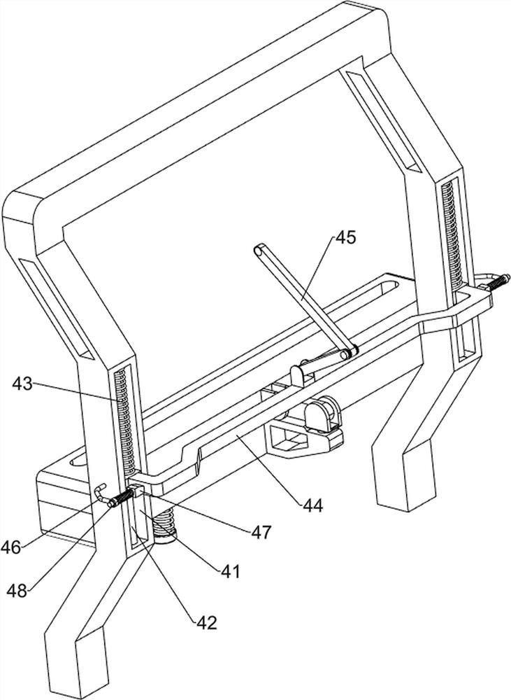
[0059] On the basis of Example 1, such as Figure 4 As shown, a positioning mechanism 4 is also included, and the positioning mechanism 4 includes a first guide rod 42, a second spring 43, a positioning plate 44, a second hinged rod assembly 45, a guide sleeve 46, a wedge block 47 and a third spring 48, The front and rear sides of the middle part of the mounting bracket 21 are all provided with first chute 41, and first guide rods 42 are arranged in the first chute 41, and a positioning plate 44 is slidably connected between the first guide rods 42, and the positioning plate 44 and A second spring 43 is connected between the first guide rods 42, a second hinged rod assembly 45 is provided in the middle of the positioning plate 44, and guide sleeves 46 are provided on the front and rear sides of the mounting frame 21, and guide sleeves 46 are slidingly arranged in the guide sleeves 46. There is a wedge-shaped block 47, and the wedge-shaped block 47 cooperates with the positioni...


PUM


Abstract

The invention relates to hardness detection equipment, in particular to material hardness detection equipment for high-end equipment manufacturing. The technical problem to be solved is to provide the material hardness detection equipment for high-end equipment manufacturing, which is convenient and can quickly detect the hardness of a material. According to the technical scheme, the material hardness detection equipment for high-end equipment manufacturing comprises a base, wherein a clamping mechanism is arranged at the top of the base; and a detection mechanism arranged on the clamping mechanism. Through the cooperation between the positioning mechanism and the measuring mechanism, the clamping mechanism can be limited after the material to be detected is placed, so that the material cannot be loosened, and a detection result can be more visually seen when the material is detected.

Description

technical field [0001] The invention relates to a hardness testing device, in particular to a material hardness testing device for high-end equipment manufacturing. Background technique [0002] Hardness, a technical term in physics, the ability of a material to locally resist hard objects being pressed into its surface is called hardness. The local resistance of a solid to the intrusion of external objects is an index for comparing the softness and hardness of various materials. It is used in the manufacture and assembly of some high-end equipment During the process, it is necessary to test the hardness of the material used to see whether its bearing capacity is up to the standard. At present, the material is directly knocked with a heavy object. Although this method can detect the hardness, it needs to be lifted manually and continuously. Putting down heavy objects is relatively cumbersome and overloads the labor. [0003] Therefore, it is necessary to design a convenient...

Claims


Application Information

Patent Timeline
Patent Type & Authority Applications(China)
IPC IPC(8): G01N3/02G01N3/04G01N3/42
CPCG01N3/02G01N3/04G01N3/42
Inventor 罗水成
Owner 罗水成
Learn More