
Bump type self-locking self-plugging rivet

A blind rivet and self-locking technology, which is applied to rivets, screws, threaded fasteners, etc., can solve the problems of low overall strength, unsafe and reliable connection, and easy loosening

Pending Publication Date: 2021-07-06
GUIZHOU HANGTAI PRECISION MFG
View PDF0 Cites 0 Cited by
  • Summary
  • Abstract
  • Description
  • Claims
  • Application Information

AI Technical Summary

Problems solved by technology

For example, the lock ring of the bulging blind rivet is not firmly locked, it is easy to loosen, and the connection is not safe and reliable.
Shear ring type blind rivets are reliable in locking, but the overall strength is low

Method used


Image

  • Bump type self-locking self-plugging rivet
  • Bump type self-locking self-plugging rivet
  • Bump type self-locking self-plugging rivet

Examples


Embodiment 1

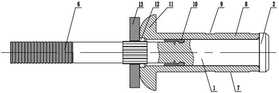
[0023] like figure 1 , 3 , 4, 5, and 6, the bulge-type self-locking blind rivet includes a nail shank 1, and the nail shank 1 is provided with a nail head 2, a locking groove 3, a broken neck groove 4 and a straight grain section 5 in sequence. , the straight section 5 is provided with a resistance washer 13, a nail sleeve 7 is provided between the resistance washer 13 and the nail head 2, and a lock ring 10 is provided between the nail sleeve 7 and the locking groove 3, when assembling , first install the lock ring 10 in the locking groove 3, then put the nail sleeve 7 on the nail rod 1, and finally push the resistance washer 13 into the 5 places of the straight grain section of the nail rod 1 so as to block the nail sleeve 7 to ensure The nail sleeve 7 cannot axially move on the nail rod 1, and finally compresses the nail sleeve 7 to strengthen the tail end and middle part of the nail sleeve 7.

[0024] For the convenience of forming a bulge, the nail sleeve 7 includes a n...

Embodiment 2

[0030] like Figure 2-6 As shown, the bulge-type self-locking blind rivet includes a nail shank 1, and the nail shank 1 is provided with a nail head 2, a locking groove 3, a broken neck groove 4 and a straight grain section 5 in sequence, and the straight grain section 5 is provided with a resistance washer 13, a nail sleeve 7 is provided between the resistance washer 13 and the nail head 2, and a lock ring 10 is provided between the nail sleeve 7 and the locking groove 3. When assembling, the lock ring 10 is first Install it in the locking groove 3, then put the nail sleeve 7 on the nail rod 1, and finally push the resistance washer 13 into the straight grain section 5 of the nail rod 1 so as to block the nail sleeve 7, so as to ensure that the nail sleeve 7 cannot be placed on the nail rod. The rod 1 moves axially, and finally presses on the nail sleeve 7 to strengthen the tail end and the middle of the nail sleeve 7 .

[0031] For the convenience of forming a bulge, the na...


PUM


Abstract

The invention discloses a bump type self-locking self-plugging rivet which comprises a rivet rod. A rivet head, a locking groove, a neck breaking groove and a straight line section are sequentially arranged on the rivet rod, a resistance gasket is arranged on the straight line section, a rivet sleeve is arranged between the resistance gasket and the rivet head, and a locking ring is arranged between the rivet sleeve and the locking groove. The bump type self-locking self-plugging rivet combines the advantages of pull riveting bump forming and self-locking and optimizes the structure, local reinforcement of the rivet sleeve is achieved through compression deformation, the manufacturing cost is low, the riveting stability is higher, due to the fact that the lock ring is formed to fill a section groove, meanwhile, the lock ring is clamped in the locking groove of the rivet rod, mutual locking force is formed, and the pre-tightening force is achieved while the rivet rod cannot be disengaged, so that the rivet rod can be applied to all skins of airplanes, automobiles and the like, polishing is not needed after riveting is completed, the rivet rod is directly flush with the outer surface of the skins, and the safe and reliable riveting performance and the high-efficiency riveting assembly requirement can be met.

Description

technical field [0001] The invention belongs to the technical field of fasteners, in particular to a bulge type self-locking blind rivet. Background technique [0002] In industrial manufacturing fields such as aerospace and automobiles, rivet connections are often used in some structural connections that do not need to be disassembled. Rivet riveting has the advantages of good connection stability and long life, but the riveting efficiency is low and the riveting strength is low. And Riveting cannot be realized in some relatively narrow spaces, which puts forward high requirements for the overall assembly. Blind rivet riveting is suitable for the narrow inner space on the surface skin. In order to ensure the strength and stability of the connection, the reliability of the riveting must be guaranteed, and the economy of the whole machine assembly must be considered. The current blind rivets have a complex structure, many influencing factors, great difficulty in manufacturin...

Claims


Application Information

Patent Timeline
Patent Type & Authority Applications(China)
IPC IPC(8): F16B19/10
CPCF16B19/1054
Inventor 谢仁君孙定彬潘新容
Owner GUIZHOU HANGTAI PRECISION MFG
Learn More