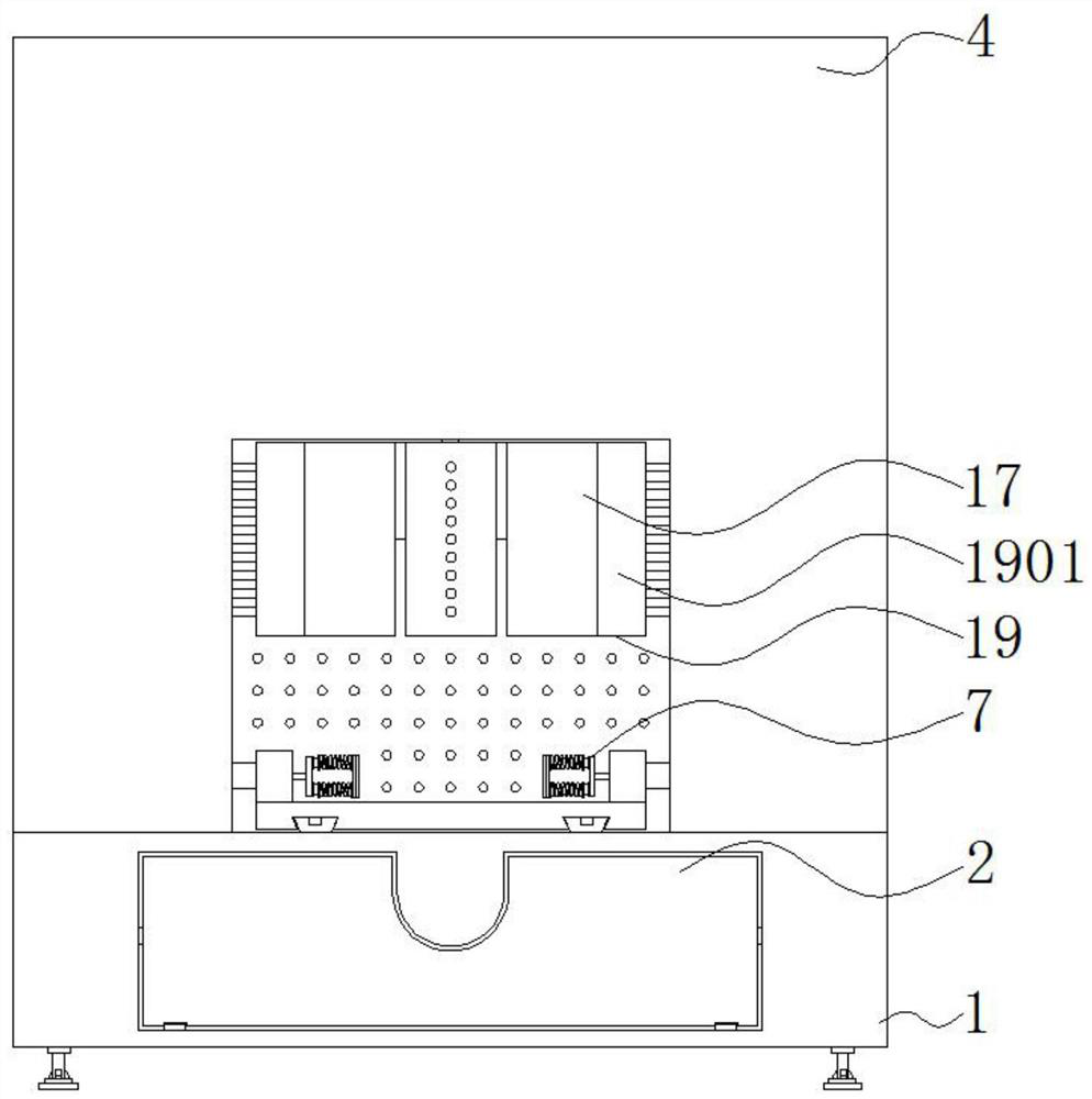
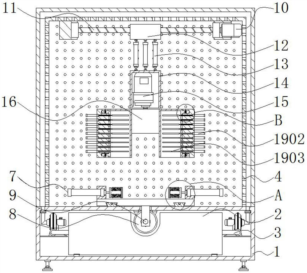
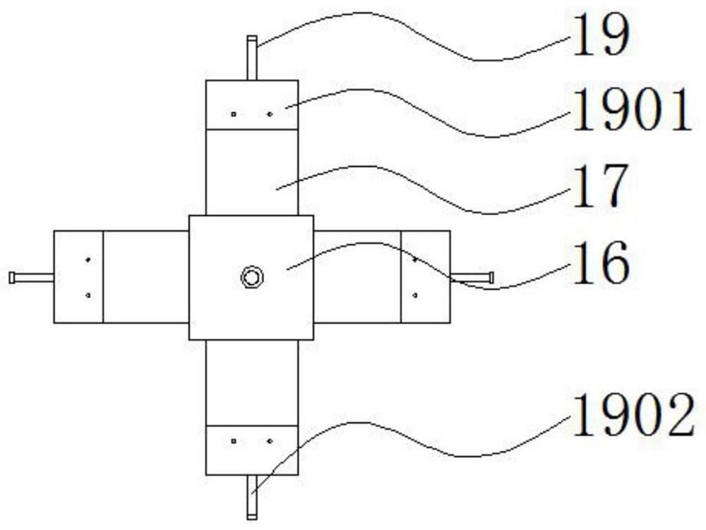
Optical filter mounting device convenient to dismount and mount and provided with angle adjusting structure

An angle adjustment structure and installation device technology, applied in the field of optical filters, can solve the problems of single function, inability to install various types of optical filters, inconvenient disassembly and assembly, etc.

Active Publication Date: 2021-07-06
NANTONG RUISEN OPTICAL CO LTD
View PDF12 Cites 0 Cited by
  • Summary
  • Abstract
  • Description
  • Claims
  • Application Information

AI Technical Summary

Problems solved by technology

[0004] The purpose of the present invention is to provide a light filter installation device with an angle adjustment structure for easy disassembly and assembly, so as to solve the problem that the existing light filter installation device proposed in the above-mentioned background technology has single function, simple structure, and inconvenient disassembly and assembly. It is inconvenient to install the optical filter, the installation efficiency is low, and it is not possible to install various types of optical filters, which cannot meet the problem of installing different types of optical filters for various products.

Method used


Image

  • Optical filter mounting device convenient to dismount and mount and provided with angle adjusting structure
  • Optical filter mounting device convenient to dismount and mount and provided with angle adjusting structure
  • Optical filter mounting device convenient to dismount and mount and provided with angle adjusting structure

Examples


Embodiment Construction

[0027] The following will clearly and completely describe the technical solutions in the embodiments of the present invention with reference to the accompanying drawings in the embodiments of the present invention. Obviously, the described embodiments are only some, not all, embodiments of the present invention.

[0028] In the description of the present invention, unless otherwise stated, the meaning of "plurality" is two or more; the terms "upper", "lower", "left", "right", "inner", "outer" , "front end", "rear end", "head", "tail", etc. indicate the orientation or positional relationship based on the orientation or positional relationship shown in the drawings, and are only for the convenience of describing the present invention and simplifying the description, rather than Nothing indicating or implying that a referenced device or element must have a particular orientation, be constructed, and operate in a particular orientation should therefore not be construed as limiting ...


PUM


Abstract

The invention relates to an optical filter mounting device convenient to dismount and mount and provided with an angle adjusting structure. The optical filter installation device comprises a base and an inner cylinder, a box body is installed below the inner wall of the base, suction fans are arranged on the two sides of the box body, a cavity sliding rail and a punching hollow shell body are sequentially arranged above the outer portion of the base from inside to outside, balls are installed in the interior of the cavity sliding rail, a clamp assembly is arranged on the exteriors of the balls, and a longitudinally-arranged motor is fixedly arranged on the upper portion of the inner wall of the base. The optical filter mounting device convenient to disassemble and assemble and provided with the angle adjusting structure has the beneficial effects that a pin sleeve in the inner cylinder and a conical pin form an elastic structure through a pin spring, the conical pin is bounced into a hole of a separation blade assembly, the inner cylinder and the separation blade assembly are mounted and connected, optical filters can be quickly filled and mounted, the plurality of optical filters are mounted at the same time, The mounting efficiency is high, the separation blade assembly can be dismounted by abutting against the conical pin, the mode for mounting and dismounting the optical filter mounting device is convenient, and firmness is achieved after installation and connection.

Description

technical field [0001] The invention relates to the technical field of optical filters, in particular to an optical filter installation device with an angle adjustment structure for easy assembly and disassembly. Background technique [0002] A filter is an optical device used to select the required radiation band. A common feature of the filter is that no filter can make the image of the celestial body brighter, because all filters will absorb certain wavelengths. In order to make the object darker, the filter installation device needs to be used when the filter is installed. [0003] The existing optical filter installation device has single function, simple structure, inconvenient disassembly and assembly, inconvenient installation when installing optical filters, low installation efficiency, and cannot install various types of optical filters, which cannot meet the installation of various products Problems with different types of filters. Contents of the invention ...

Claims


Application Information

Patent Timeline
IPC IPC(8): B23P19/04B23P19/00B08B5/04
CPCB23P19/04B23P19/006B08B5/04
Inventor 杨爱梅王森林
Owner NANTONG RUISEN OPTICAL CO LTD
Why Eureka
Try Eureka