
Microwave reverberation chamber and use method thereof

A reverberation chamber and microwave technology, applied in the direction of the casing of the measuring device, can solve the problems of complicated corrugated wall processing, inability to meet requirements, difficult test adjustment, etc. Effect

Pending Publication Date: 2021-07-02
芜湖麦可威电磁科技有限公司
View PDF0 Cites 0 Cited by
  • Summary
  • Abstract
  • Description
  • Claims
  • Application Information

AI Technical Summary

Problems solved by technology

Commonly used microwave reverberation chambers include mechanical agitation reverberation chambers, corrugated wall reverberation chambers, etc. Mechanical agitation reverberation chambers have the disadvantages of complex structure and large space occupation, while the corrugated walls of corrugated wall reverberation chambers are complicated to process, and the test adjustment difficulty
In some projects that require small volume and tight processing cycle, the previous design can no longer meet the requirements

Method used


Image

  • Microwave reverberation chamber and use method thereof
  • Microwave reverberation chamber and use method thereof
  • Microwave reverberation chamber and use method thereof

Examples


Embodiment Construction

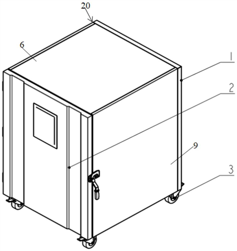
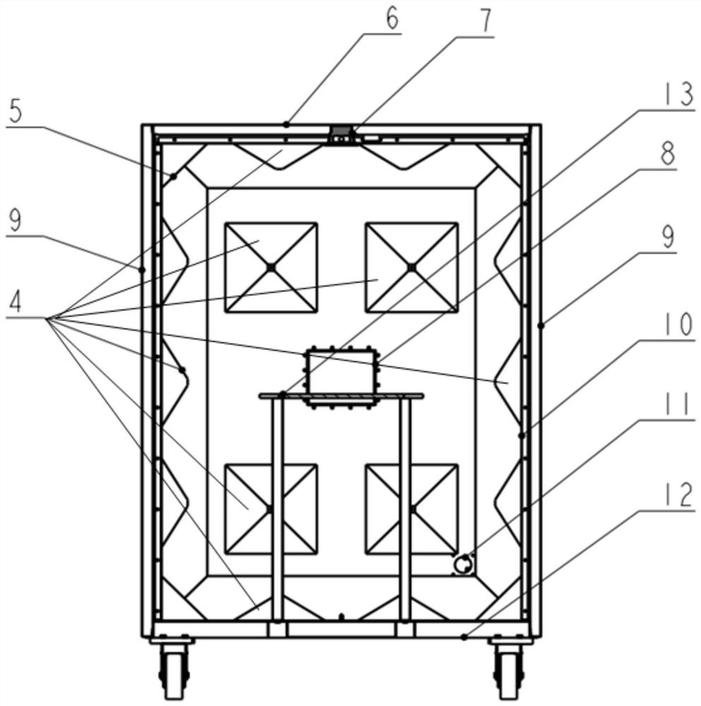
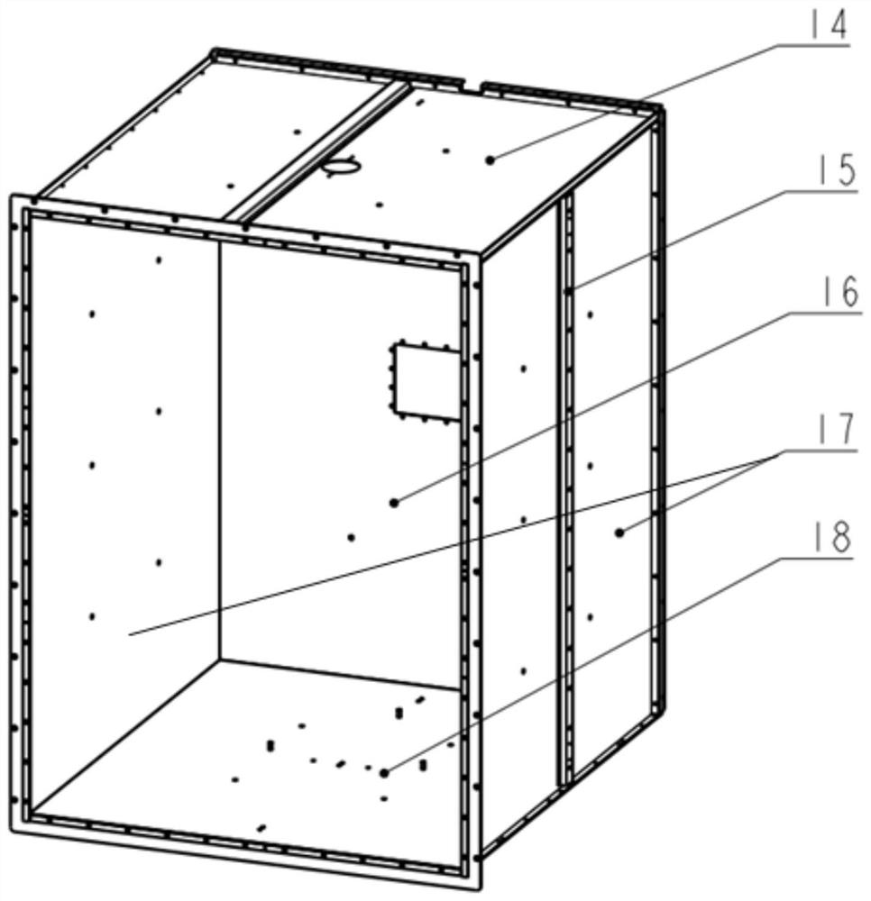
[0029] In the present invention, it should be understood that the terms "length"; "width"; "upper"; "lower"; "front"; "back"; "left"; "right"; "vertical"; "; "Top"; "Bottom" "Inner"; "Outer"; "Clockwise"; "Counterclockwise"; "Axial"; "Plane Direction"; The orientations or positional relationships shown in the drawings are only for the convenience of describing the present invention and simplifying the description, rather than indicating or implying that the referred device or element must have a specific orientation; it is constructed and operated in a specific orientation, so it cannot be understood as Limitations on the Invention.

[0030] Such as Figure 1 to Figure 6 As shown, a microwave reverberation chamber includes an outer casing 20, an inner cavity body 10, a storage platform 13 and a reflector, the outer casing 20 covers the outside of the inner cavity body 10, and the object storage platform 13 is installed in the inner cavity body In 10, the reflector is arrange...


PUM


Abstract

A microwave reverberation chamber disclosed by the invention comprises an outer shell, an inner cavity, a placement platform and reflectors, the outer shell wraps the outer side of the inner cavity, the placement platform is installed in the inner cavity, and the reflectors are arranged on the inner wall of the inner cavity. According to the microwave reverberation chamber, the double-layer cavity structure is adopted, the inner-layer structure and the outer-layer structure are clear in division of labor, the inner cavity is a flat inner cavity, conditions are provided for conveniently installing the reflectors on the inner cavity, and meanwhile the shielding performance of the microwave reverberation chamber is improved through the double-layer structure; the inner cavity is provided with a plurality of inclined plane reflectors which are independently mounted, so that parallel surfaces of a box body are reduced, scattering inclined planes are increased, a microwave field in the cavity is more uniform, and the reflectors are simple in structure, convenient to manufacture and low in cost. The invention further discloses a use method of the microwave reverberation chamber.

Description

technical field [0001] The invention belongs to the technical field of microwave equipment, and in particular relates to a microwave reverberation chamber and a using method thereof. Background technique [0002] With the development of science and technology, microwave reverberation chambers have been widely used in the field of microwave heating technology, and there are many types. Commonly used microwave reverberation chambers include mechanical stirring reverberation chambers, corrugated wall reverberation chambers, etc. Mechanical stirring reverberation chambers have the disadvantages of complex structure and large space occupation, while the corrugated walls of corrugated wall reverberation chambers are complicated to process, and the test adjustment difficulty. In some projects that require small volume and tight processing cycle, the previous design can no longer meet the requirements. Contents of the invention [0003] Aiming at the deficiencies in the prior ar...

Claims


Application Information

Patent Timeline
Patent Type & Authority Applications(China)
IPC IPC(8): G01R1/04
CPCG01R1/04
Inventor 李成王有利史中梁
Owner 芜湖麦可威电磁科技有限公司
Learn More