
Prediction result identification method, prediction result identification model training method, prediction result identification model training device and computer storage medium

A technology for predicting results and identification, applied in the field of sample identification, can solve the problems of increasing false positives, low-quality positive and negative samples, and small target positive samples, and achieves the effect of avoiding cold start and improving training performance.

Pending Publication Date: 2021-06-29
SHANGHAI CLOUDWALK HUILIN ARTIFICIAL INTELLIGENCE TECH CO LTD
View PDF0 Cites 0 Cited by
  • Summary
  • Abstract
  • Description
  • Claims
  • Application Information

AI Technical Summary

Problems solved by technology

[0003] However, there are two shortcomings in this positive and negative sample distribution method: first, it depends on the design of the anchor point, and the design of the anchor point is prone to blunt shortcomings due to manual generation, for example, the positive sample that is easy to cause large targets to be matched Many and small targets are matched with fewer positive samples; second, when assigning positive samples, due to the existence of occlusion, the center of the anchor point assigned to a real target frame may actually fall on another target
However, this distribution method of positive and negative samples still has the following disadvantages: first, a large number of low-quality positive and negative samples are introduced in the training process, which is not conducive to the optimization of the network; second, the loss weight of negative samples is reduced, which may increase false positive risk

Method used


Image

  • Prediction result identification method, prediction result identification model training method, prediction result identification model training device and computer storage medium
  • Prediction result identification method, prediction result identification model training method, prediction result identification model training device and computer storage medium
  • Prediction result identification method, prediction result identification model training method, prediction result identification model training device and computer storage medium

Examples


no. 1 example

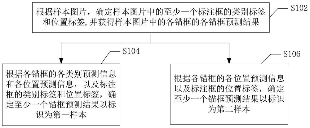
[0033] figure 1 The processing flow of the prediction result identification method in the first embodiment of the present application is shown. As shown in the figure, the prediction result identification method in this embodiment mainly includes:

[0034] Step S102, according to the sample picture, determine the category label and position label of at least one labeled box in the sample picture, and obtain the prediction results of each anchor box in the sample picture.

[0035] In this embodiment, the label frame is used to identify at least one target object in the sample picture; the category label of the label frame is used to identify the category of the target object (for example: people, animals, plants, buildings, etc.); the sample picture The location label is used to identify the location of each object in the sample image.

[0036] In this embodiment, the reference model is a picture recognition model with a picture recognition function.

[0037] In this embodime...

no. 2 example

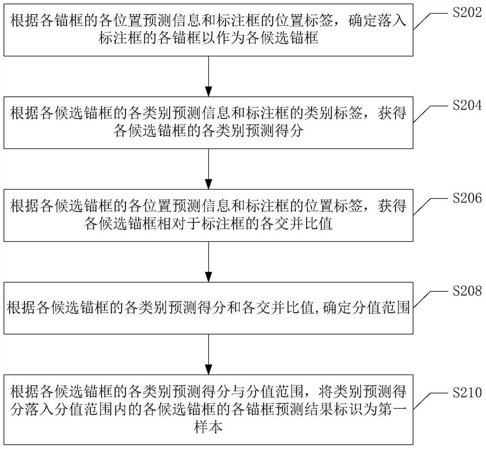
[0048] figure 2 The processing flow of the prediction result identification method according to the second embodiment of the present application is shown. This embodiment mainly shows the specific implementation scheme of the first sample identification. As shown in the figure, the prediction result identification method of this embodiment mainly includes:

[0049] Step S202, according to each position prediction information of each anchor frame and the position label of the annotation frame, determine each anchor frame falling into the annotation frame as each candidate anchor frame.

[0050] In this embodiment, when there are multiple annotation frames in the sample picture (that is, when there are multiple objects in the sample image), one annotation frame is selected in turn, and each anchor frame is compared with the currently selected annotation frame respectively. Perform comparative analysis.

[0051] In this embodiment, each anchor frame falling into the annotation...

no. 3 example

[0064] image 3 It shows the processing flow of the prediction result identification method of the third embodiment of the present application. This embodiment shows the specific implementation scheme of the second sample identification. As shown in the figure, the prediction result identification method of this embodiment mainly includes:

[0065] Step S302, according to each position prediction information of each anchor frame and the position label of the annotation frame, each intersection ratio of each anchor frame relative to the annotation frame is obtained.

[0066] In this embodiment, according to the location prediction information of each anchor frame and the location label of the annotation frame, the intersection ratio between all the anchor frames and the annotation frame can be calculated.

[0067] Step S304: According to each intersection and union ratio of each anchor box and a preset threshold, the anchor frame prediction results of each anchor frame whose in...


PUM


Abstract

A prediction result identification method, a prediction result identification model training method, a prediction result identification model training device and a computer storage medium mainly comprise the steps of determining a category label and a position label of an annotation box in a sample picture according to the sample picture, obtaining each anchor frame prediction result of each anchor frame in the sample picture, and obtaining each anchor frame prediction result of each anchor frame; according to each category prediction information and each position prediction information of each anchor frame, and according to the category label and the position label, determining at least one anchor frame prediction result to be identified as a first sample; according to the position prediction information of each anchor frame and the category label and the position label of the labeling frame, determining at least one anchor frame prediction result to be identified as a second sample. Therefore, better positive and negative sample distribution reference can be obtained, and the training performance of the model can be optimized.

Description

technical field [0001] The embodiments of the present application relate to the technical field of sample identification, and more specifically, to a prediction result identification and its model training method, device and computer storage medium. Background technique [0002] In the current target detection based on deep learning, the distribution of positive and negative samples is generally based on the intersection ratio of the predefined anchor point and the real target frame. A positive threshold and a negative threshold are set. When the intersection of the anchor point and the real target frame When the union ratio is greater than the positive threshold, the sample is a positive sample, and when it is smaller than the negative threshold, the sample is a negative sample. [0003] However, there are two shortcomings in this positive and negative sample distribution method: first, it depends on the design of the anchor point, and the design of the anchor point is pron...

Claims


Application Information

Patent Timeline
IPC IPC(8): G06K9/62G06K9/32
CPCG06V10/25G06F18/2431G06F18/2415G06F18/214
Inventor 薛星源
Owner SHANGHAI CLOUDWALK HUILIN ARTIFICIAL INTELLIGENCE TECH CO LTD
Learn More