Energy-saving environment-friendly plug-flow type aeration tank

An energy-saving and environmentally friendly push-flow technology, which is applied in water/sludge/sewage treatment, biological water/sewage treatment, mechanical equipment, etc., can solve problems such as weak impact resistance, low energy recovery efficiency, and unstable power generation. , to achieve the effect of high stability, simple structure, easy adjustment and maintenance

Pending Publication Date: 2021-06-29
SHANGHAI JIAO TONG UNIV
View PDF7 Cites 1 Cited by
  • Summary
  • Abstract
  • Description
  • Claims
  • Application Information

AI Technical Summary

Problems solved by technology

However, this patented technology mainly uses microbial redox to generate power. Its application is greatly affected by working conditions (pH, temperature), weak impact resistance, high requirements for microbial activity, unstable power generation and low energy recovery efficiency.

Method used


Image

  • Energy-saving environment-friendly plug-flow type aeration tank
  • Energy-saving environment-friendly plug-flow type aeration tank
  • Energy-saving environment-friendly plug-flow type aeration tank

Examples


Embodiment 1

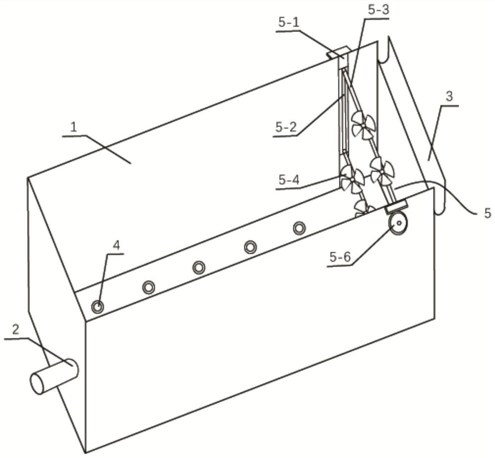
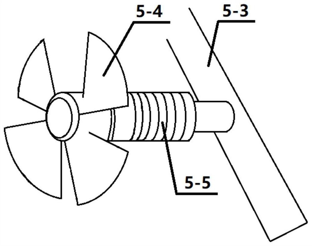
[0022] Such as figure 1 As shown, an energy-saving and environment-friendly plug-flow aeration tank includes a tank body 1, a water inlet 2, a water outlet 3, an aeration device 4 and a power generation device 5, and the power generation device 5 includes a slide rail 5-1, a vertical Rod 5-2, connecting shaft 5-3, impeller 5-4, generator 5-5 and transmission device 5-6, the slide rail 5-1 is longitudinally installed on the inner wall of the pool near the end of the water outlet 3 of the pool body 1 The vertical bar 5-2 is detachably inserted into the corresponding slide rail; the transmission device 5-6 is arranged on the slide rail 5-1 and connected with the upper end of the vertical bar 5-2; The connecting shaft 5-3 is vertically connected to a pair of the vertical rods 5-2 for fixing the impeller 5-4 and the generator 5-5, and can be driven to move up and down by the transmission device 5-6 to adjust the height.

[0023] The impeller 5-4 is connected to the rotating shaft ...

Embodiment 2

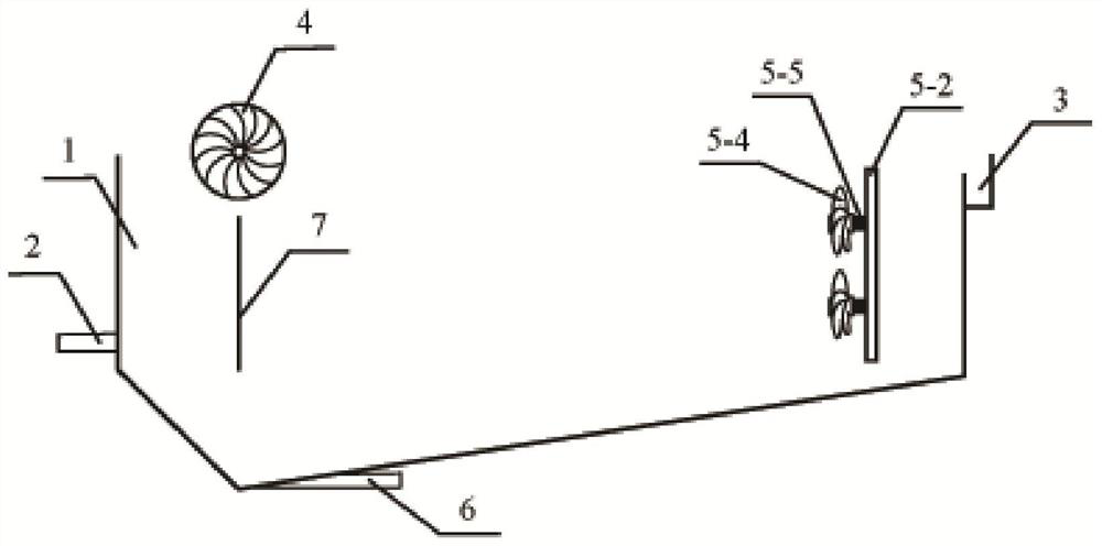
[0030] Such as figure 2 As shown, the present invention proposes an energy-saving and environment-friendly push-flow aeration tank, its aeration device 4 adopts mechanical aeration facilities, and is installed on the surface water surface near the water inlet 2 in the tank body 1; There is a sludge outlet 6 for collecting sludge; the side of the tank body 1 close to the water inlet 2 is provided with a retaining wall 7, which is used to guide the water inlet to the area near the aeration device 4, and at the same time, the water carried by the water Sediment and large particle sludge are separated to the bottom sludge outlet 6. The vertical distance between the bottom of the retaining wall 7 and the bottom of the pool body 1 is 0.5m. Adopt the same power generation device 5 and use mode as in Example 1 to process domestic sewage containing COD 540mg / L, TN60mg / L, SS 220mg / L, the water flow velocity in the aeration tank is 0.5m / s, and the sewage electricity production voltage ...

Embodiment 3

[0032] In the pool body 1, two pairs of vertical bars 5-2 are arranged in parallel along the water flow direction, and the distance between the two pairs of vertical bars is 1m. Other installation methods, operating conditions and sewage water quality are consistent with Embodiment 1, and the electricity generation voltage of sewage is 11-2. 17V, current 0.1-0.41A, effluent COD removal rate is 76%, TN removal rate is 50%, SS removal rate is 70%.


PUM


Abstract

The invention relates to an energy-saving environment-friendly plug-flow type aeration tank. The aeration tank comprises a tank body (1), wherein a water inlet (2) is formed in one end of the tank body (1), a water outlet (3) is formed in the other end of the tank body (1), an aeration device (4) is arranged at the bottom of the tank body (1), a power generation device (5) is arranged on the inner wall of the end, close to the water outlet (3), of the tank body (1), sewage enters the tank body (1) from the water inlet (2) and continuously rolls and flows under the action of the aeration device (4), and purified water pushes the power generation device (5) to generate power and then is discharged from the water outlet (3). Compared with the prior art, the aeration tank of the invention has the advantages that kinetic energy of water flow in the aeration tank is utilized, and an impeller rotates under the impact of the water flow, so a motor is driven to generate power, and the power is continuously collected and stored in storage equipment. The aeration tank is simple in structure, easy to adjust and maintain, free of influence of seasons or climate factors and the like on the power generation amount, high in use stability and capable of being widely applied and popularized in various sewage treatment plants.

Description

technical field [0001] The invention relates to the field of sewage treatment, in particular to an energy-saving and environment-friendly plug-flow aeration tank. Background technique [0002] Due to the limited resources of the earth, the environmentally friendly energy generation methods currently used by people include solar power generation, hydropower generation and wind power generation, etc., and have been widely used. Due to factors such as power generation stability and huge construction projects, it is very important to develop and utilize other simple, stable and environmentally friendly energy power generation methods. [0003] At the end of 2019, the cumulative number of sewage treatment plants in my country's cities and counties reached 12,893, with a total daily treatment capacity of 228.46 million tons. With economic development, the number of construction and disposal scale of sewage treatment plants in my country is constantly increasing. The activated slu...

Claims


Application Information

Patent Timeline
IPC IPC(8): C02F3/12F03B13/00
CPCC02F3/12C02F3/1278F03B13/00Y02W10/10
Inventor 王晓宁朱南文
Owner SHANGHAI JIAO TONG UNIV
Why Eureka
Try Eureka