
Airborne circuit of multi-rotor unmanned aerial vehicle

A multi-rotor UAV and circuit technology, which is applied to circuit devices, battery circuit devices, current collectors, etc., can solve problems such as reducing the load capacity of multi-rotor UAVs and affecting the flight performance of multi-rotor UAVs.

Active Publication Date: 2021-06-25
福建清航装备科技有限公司
View PDF7 Cites 0 Cited by
  • Summary
  • Abstract
  • Description
  • Claims
  • Application Information

AI Technical Summary

Problems solved by technology

[0004] The technical problem to be solved in this application is to provide a multi-rotor UAV onboard circuit to solve the current problem. Load capacity, issues that affect the flight performance of multi-rotor UAVs

Method used


Image

  • Airborne circuit of multi-rotor unmanned aerial vehicle
  • Airborne circuit of multi-rotor unmanned aerial vehicle
  • Airborne circuit of multi-rotor unmanned aerial vehicle

Examples


Embodiment Construction

[0022] In order to enable those skilled in the art to better understand the solution of the present application, the technical solution in the embodiment of the application will be clearly and completely described below in conjunction with the accompanying drawings in the embodiment of the application. Obviously, the described embodiment is only It is a part of the embodiments of this application, not all of them. Based on the embodiments in this application, all other embodiments obtained by persons of ordinary skill in the art without making creative efforts belong to the scope of protection of this application.

[0023] The inventor of the present application has found through research that at present, when a voltage reducer is mounted on a multi-rotor UAV, and the voltage of the motor is reduced by using the voltage reducer, due to the certain weight of the voltage reducer, the method of carrying a voltage reducer is used to reduce the voltage of the motor. When the load v...


PUM


Abstract

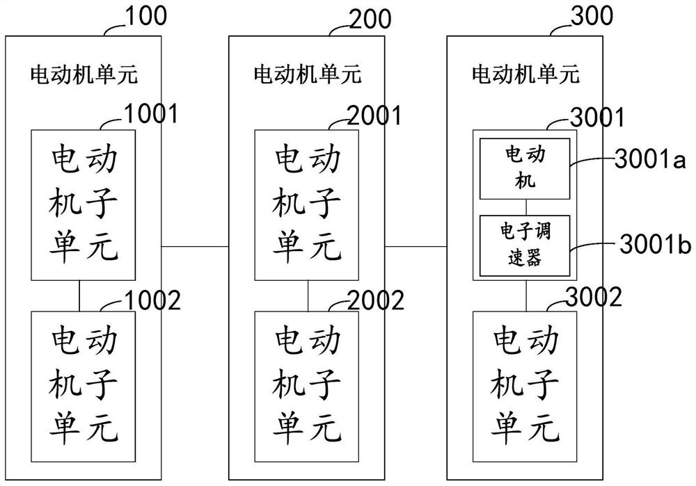
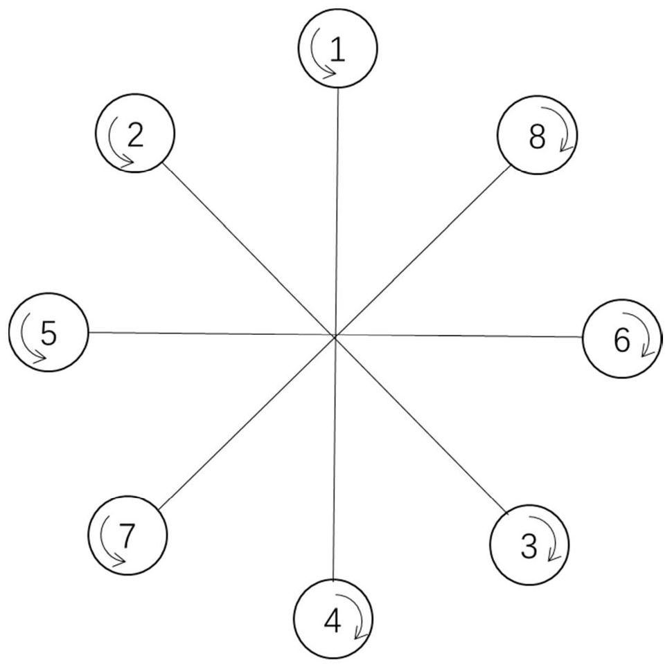
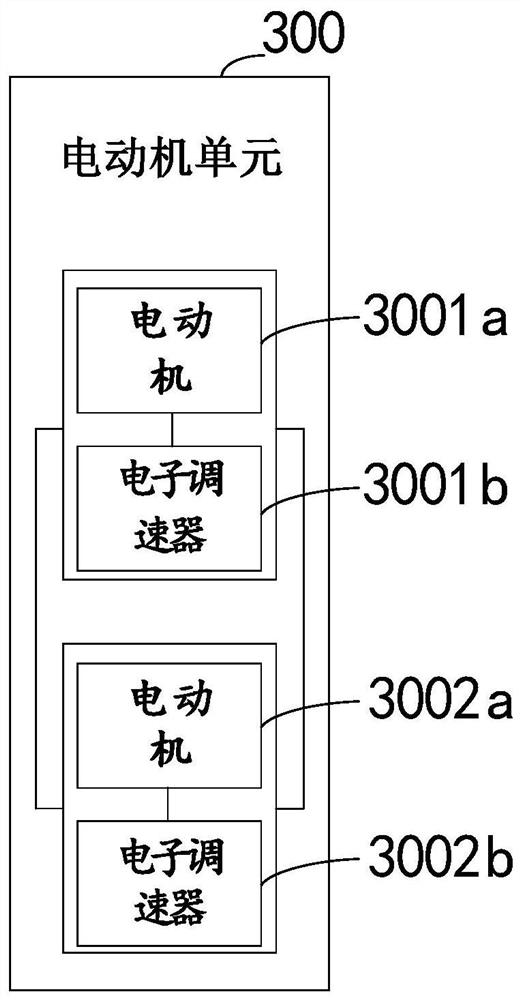
The invention discloses an airborne circuit of a multi-rotor unmanned aerial vehicle. The circuit comprises a plurality of motor units which are connected in series. Each motor unit comprises at least two motor subunits, wherein each motor subunit comprises a motor and an electronic speed regulator, and the motor is connected with the electronic speed regulator; the two motor subunits are connected; and motors of each motor unit are respectively positioned on symmetrical arms of the multi-rotor unmanned aerial vehicle.

Description

technical field [0001] This application relates to the field of UAV onboard circuit design, in particular to a multi-rotor UAV onboard circuit. Background technique [0002] At present, multi-rotor UAVs are widely used, involving many industries such as fire protection, investigation, plant protection, and transportation. Each rotor of the multi-rotor UAV is connected to a motor that controls the rotation of the rotor. The motors are connected in parallel and powered by the on-board power supply of the multi-rotor UAV. It should be noted that the voltage of the on-board power supply for the motor is usually large, which may exceed the rated voltage of the rotor motor. The UAV is equipped with a voltage reducer, which is used to reduce the voltage of the motor. [0003] However, due to the weight of the voltage reducer, when the voltage carried by the motor is reduced by using a voltage reducer, the load capacity of the multi-rotor UAV will inevitably be reduced, and the fl...

Claims


Application Information

Patent Timeline
Patent Type & Authority Applications(China)
IPC IPC(8): H02P5/00H02J7/34
CPCH02P5/00H02J7/345Y02T50/60
Inventor 王贤宇印明威海日汗包长春徐震翰李京阳
Owner 福建清航装备科技有限公司
Learn More