A 5g communication base station power operation monitoring system

A technology for operation monitoring and communication base station, which is applied in substation/power distribution device casing, electrical components, substation/switch layout details, etc., and can solve problems affecting the sensitivity of wiring connection and entering the cavity, etc.

Active Publication Date: 2022-07-19
深圳市尤纳斯技术有限公司
View PDF4 Cites 0 Cited by
  • Summary
  • Abstract
  • Description
  • Claims
  • Application Information

AI Technical Summary

Problems solved by technology

[0004] The power monitoring system needs to be interspersed with wires to make the system operate in the energized state. Since the wire hole is in a hollow state without wiring, and the box-type power monitoring system is usually placed outdoors, it is easy for foreign objects such as dust and impurities to enter through the wire hole. In the cavity, during the cross-wiring operation, it will be pushed into the box by the connecting port, which will affect the sensitivity of the wiring

Method used


Image

  • A 5g communication base station power operation monitoring system
  • A 5g communication base station power operation monitoring system
  • A 5g communication base station power operation monitoring system

Examples


Embodiment 1

[0031] as attached figure 1 to the attached Figure 7 shown:

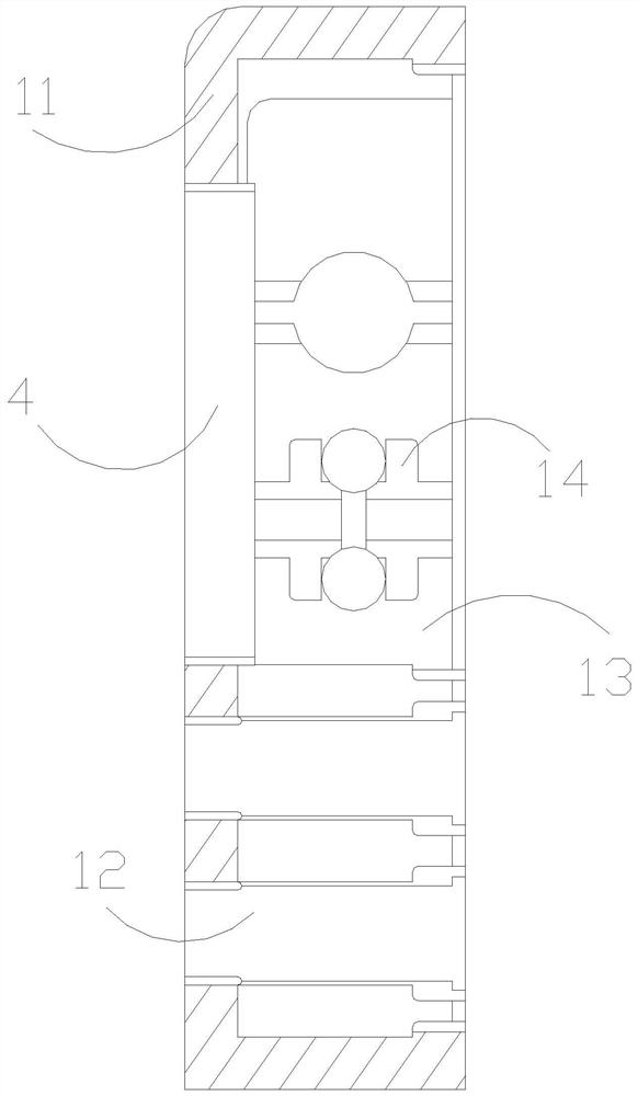
[0032] The present invention provides a 5G communication base station power operation monitoring system, the structure of which is provided with a front box 1, a whole box 2, a top roller 3, and a display screen 4. The whole box 2 is installed at the rear end of the front box 1, and the top box The roller 3 is located on the top of the whole box 2 , and the display screen 4 and the front box 1 are of an integrated structure and are arranged in the upper and middle position of the front end of the display screen 4 .

[0033] The front box 1 is provided with a box frame 11, a wiring channel 12, an inner slot 13, and a connecting wire 14. The inner box slot 13 and the box frame 11 are an integrated structure and are located on the inner side thereof. 12 is set at the lower position of the front box 1, and the through wire 14 is embedded and connected in the upper middle position in the inner groove 13 of the box.

...

Embodiment 2

[0041] as attached Figure 8 to the attached Figure 9 shown:

[0042] Wherein, the block a4 is provided with a fixed frame a41, a cavity a42, a spring steel a43, and a turning device a44, the cavity a42 is located inside the fixed frame a41, and the spring steel a43 is embedded and connected inside the cavity a42, One end of the spring steel a43 is connected with the inner end of the swinging device a44 and cooperates movably. The cavity a42 is in the state of an empty groove. Under the elastic cooperation of the spring steel a43, it swings to the outer end of the cavity a42.

[0043] The swinging device a44 is provided with a rear swing rod w1, a hinge rod w2, a wiping block w3, a rebound block w4, and a pull spring w5. The rear swing rod w1 is hingedly connected to the lower end of the hinge rod w2, and the wiping block w3 Connected to one side of the hinge rod w2, the rebound block w4 is embedded and movable inside the wiper block w3, the pull spring w5 is connected bet...


PUM


Abstract

The invention discloses a power operation monitoring system for a 5G communication base station. Its structure is provided with a front box, a whole box, a top roller and a display screen. The front box is an integrated structure and is located in the upper middle of its front end. The block is not subject to the front end extrusion force. Under the action of the repulsive magnetic force of the magnetic blocks, the ligament blocks are stretched out, and the connecting plate is extended to match the ligament blocks. The extension activity is generated, and the diagonal support is generated at the angle between the side support block and the stop block, so that there is a certain angle between the side support block and the stop block, which is convenient for the stop block to be swung up and in a vertical state. The rod cooperates with the arc block to make an arc-like extension, so that the side support block is gradually reset to a lateral umbrella-like structure and has a driving force for pulling and swinging the lower rod frame, which is convenient for the change rod to be stretched and folded. The bottom wheel further assists the change rod Displacement during the expansion and contraction process, and then drives the whole movable body to have displacement movement during the flipping process, and has a front port blocking effect on the insertion cavity.

Description

technical field [0001] The invention belongs to the field of 5G communication base stations, and more specifically, relates to a power operation monitoring system for 5G communication base stations. Background technique [0002] With the development of science and technology, 5G occupies an important position in modern communication technology. The power operation monitoring system plays a core role in the monitoring of communication power distribution and distribution. It monitors and controls the power production process, and implements real-time data detection and control for the power operation of communication base stations. Monitoring, instead of manual work, needs to be fixed in the monitoring center to monitor the operation of the substation and distribution site. [0003] Based on the above findings of the present inventors, the existing 5G communication base station power operation monitoring system has the following deficiencies: [0004] The power monitoring sys...

Claims


Application Information

Patent Timeline
Patent Type & Authority Patents(China)
IPC IPC(8): H02B1/46H02B1/28H02B1/20
CPCH02B1/46H02B1/28H02B1/202
Inventor 董晓杰
Owner 深圳市尤纳斯技术有限公司
Why Eureka
Try Eureka